Connecting the Input/Output Signals
Cue Tone/Cue Trigger Interface
The D9824 receiver is equipped with a connector labeled Cue Tone/Relay for alarm
relay outputs for remote alarm signaling. This connector provides Cue Tone, Cue
Trigger and Alarm relay functionality. These outputs are user-configurable via the
Setup Menu on the front panel.
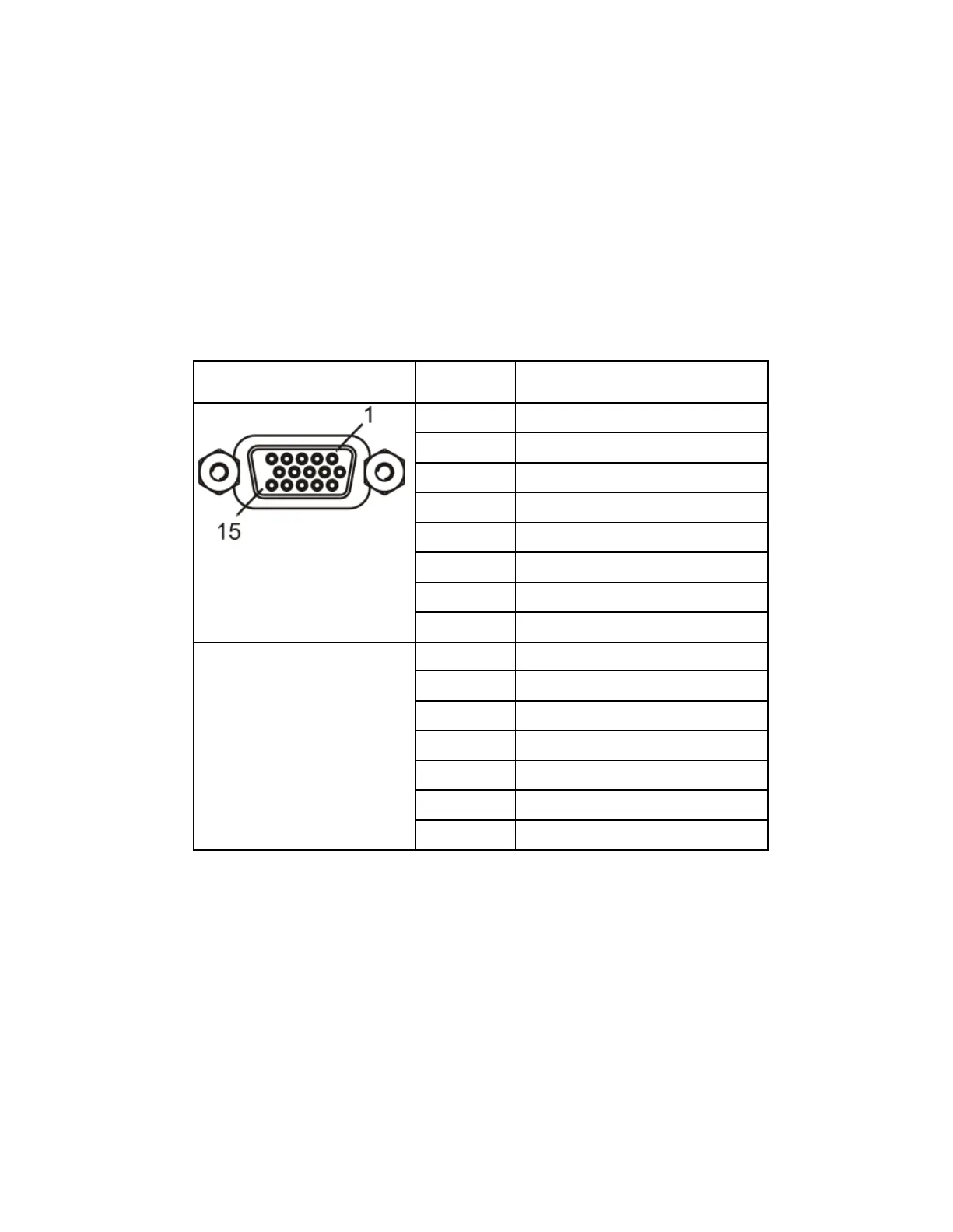
The connector is a 15-pin sub-D female connector. The following diagram shows the
connector and the pin allocation table for Cue Tone, Cue Trigger and Alarm relay
connections.
Connecting the Cue Tone Interface
Connect the Cue Tone pins, 13 and 14 to a device to facilitate ad-insertion using
DTMF Analog Cue Tones.
Connecting the Cue Trigger Interface
Connect the Cue Trigger pins (1 to 8) to up to 8 serial control devices or a device to
control ad-insertion. These outputs are user-configurable on the front panel menu.