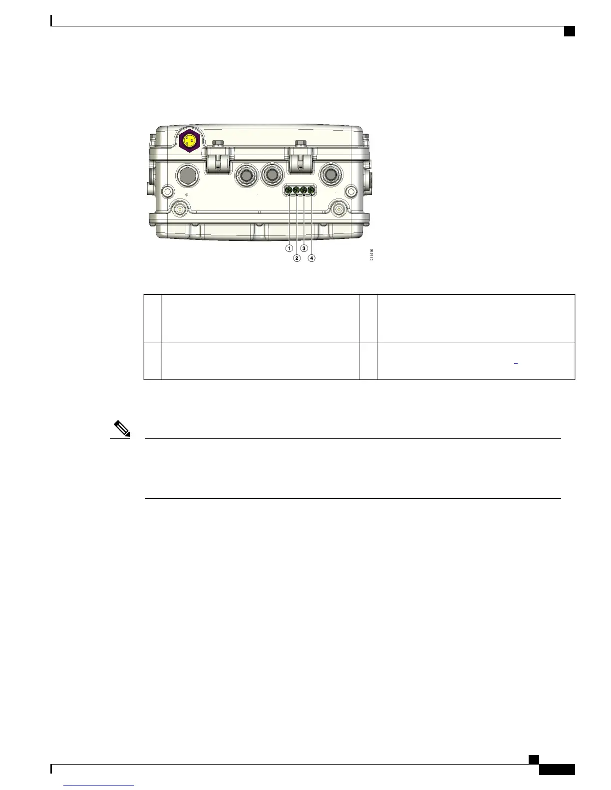
This figure shows the location of the AP1500 LEDs.
Figure 7: Access Point LEDs at the Bottom of the Unit
The table below describes each LED and its status.
RF-1 LED—Status of the radio in slot 0
(2.4-GHz) and slot 2 (5.8-GHz for 1524SB and
4.9-GHz for 1524PS)).
3Status LED—Access point and software status1
RF-2 LED—Status of the radio in slot 1
(5.8-GHz) and the radio in slot 3.
1
4Uplink LED—Ethernet, cable, or fiber status2
1
Slot 3 is disabled
The RF-1 and RF-2 LEDs monitor two radios simultaneously but do not identify the affected radio. For
example, if the RF-1 LED displays a steady red LED, one or both of the radios in slots 0 and 2 have
experienced a firmware failure. To identify the failing radio, you must use other means, such as the access
point CLI or controller GUI to investigate and isolate the failure.
Note
Table 4: Access Point LED Signals , on page 20 lists the access point LED signals.
Cisco Mesh Access Points, Design and Deployment Guide, Release 7.3
OL-27593-01 19
Mesh Network Components
Cisco Outdoor Mesh Access Points