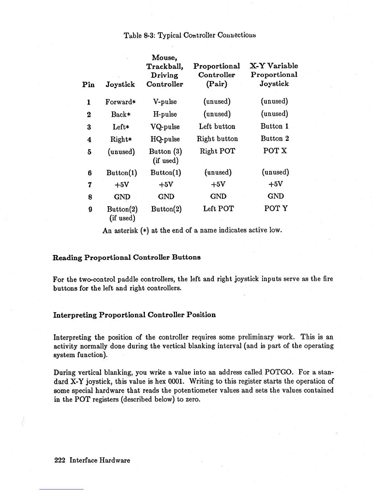
Table 8-3: Typical Controller
COllllectiol1l:s
Mouse,
Trackball,
Proportional
X-
Y
Variable
Driving
Controller
Proportional
Pin
Joystick
Controller
(Pair)
Joystick
1
Forward*
V-pulse
(unused)
(unused)
2 Back*
H-pulse
(unused)
(unused)
3 Left*
VQ-pulse
Left
button
Button 1
4
Right*
HQ-pulse
Right
button
Button 2
5
(unused)
Button
(3)
Right
POT POT
X
(if used)
6
Button(l)
Button(!)
(unused) (unused)
7
+5V
+5V
+5V
+5V
8
GNp
GND
GND GND
9
Button(2)
Button(2)
Left
POT
POTY
(if used)
An asterisk
(*)
at
the end of a name indicates active low.
Reading
Proportional
Controller
Buttons
For
the two-control paddle controllers, the left and right joystick inputs serve as the
fire
buttons for the left and right controllers.
Interpreting
Proportional
Controller
Position
Interpreting the position of the controller requires some preliminary work. This is an
activity normally done during the vertical blanking interval (and
is
part
of the operating
system function).
During vertical blanking, you write a value into an address called POTGO.
For
a stan-
dard
X-Y joystick, this value is hex 0001. Writing
to
this register
starts
the operation of
some special hardware
that
reads the potentiometer values and sets the values contained
in the
POT
registers (described below) to zero.
222 Interface Hardware