>
DDFSTRT
DDFSTOP
DMACON
DMACONR
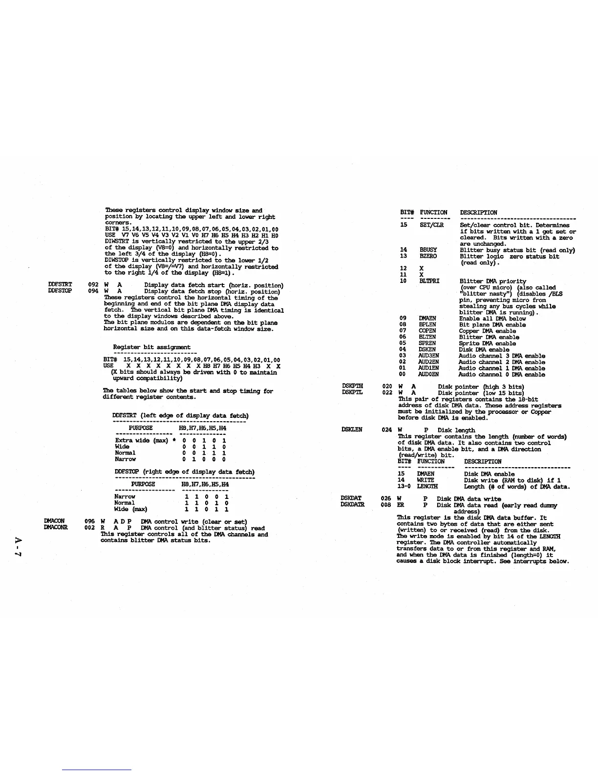
These
registers
control
display
window
size
and
position
by
locating
the
upper
left
and
lower
right
corners.
BIT#
15,14,13,12,11,10,09,08,07,06,05,04,03,02,01,00
USE
V7 V6
V5
V4 V3 V2
VI
VO
H7 H6
HS
H4
H3
H2
HI
HO
DIWSTRT
is
vertically
restricted
to
the
upper
2/3
of
the
display
(V8=0)
and
horizontally
restricted
to
the
left
3/4
of
the
display
(H8=0).
DIWSTOP
is
vertically
restricted
to
the
lower
1/2
of
the
display
(V8=/=V7)
and
horizontally
restricted
to
the
right
1/4
of
the
display
(H8=1).
092 W A
Display
data
fetch
start
(horiz.
position)
094 W A
Display
data
fetch
stop
(horiz.
position)
These
registers
control
the
horizontal
timing
of
the
beginning
and
end
of
the
bit
plane
DMA
display
data
fetch.
The
vertical
bit
plane
DMA
timing
is
identical
to
the
display
windows
described
above.
The
bit
plane
modu1os
are
dependent
on
the
bit
plane
horizontal
size
and
on
this
data-fetch
window
size.
Register
bit
assignment
BIT#
15,14,13,12,11,10,09,08,07,06,05,04,03,02,01,00
~
XXXXXXXX~H7~HS~IDXX
(X
bits
should
always
be
driven
with
°
to
maintain
upward
conpatibility)
The
tables
below
show
the
start
and
stop
timing
for
different
register
contents.
DDFSTRT
(left
edge
of
display
data
fetch)
PURPOSE
~,H7,H6,HS,H4
Extra
wide
(max)
* ° ° 1 ° 1
Wide 0 0 1 1
°
Normal ° ° 1 1 1
Narrow 0 1 0 0 0
DDFSTOP
(right
edge
of
display
data
fetch)
PURPOSE
Narrow
Normal
Wide
(max)
~,H7
,H6,HS,H4
11001
11010
11011
096
WAD
P
DMA
control
write
(clear
or
set)
002
RAP
DMA
control
(and
blitter
status)
read
This
register
controls
all
of
the
DMA
channels
and
contains
blitter
DMA
status
bits.
DSKPTH
DSKPlL
DSKLEN
DSKDAT
DSKDATR
BIT#
FUNCTION
15
14
13
12
11
10
09
08
07
06
05
04
03
02
01
00
SET/CLR
BBUSY
BZERO
X
X
BLTPRI
DMAEN
BPLEN
COPEN
BLTEN
SPREN
DSKEN
AUD3EN
AUD2EN
AUDlEN
AUDOEN
DESCRIPTION
Set/clear
control
bit.
Determines
if
bits
written
with
a 1
get
set
or
cleared.
Bits
written
with
a
zero
are
unchanged.
Blitter
busy
status
bit
(read
only)
Blitter
logic
zero
status
bit
(read
only)
•
Blitter
DMApriority
{over
CPU
micro)
(also
called
'bUtter
nasty")
(disables
/BLS
pin,
preventing
micro
from
stealing
any
bus
cycles
while
blitter
DMA
is
running).
Enable
all
DMA
below
Bit
plane
DMA
enable
Copper
DMA
enable
B1itter
DMA
enable
Sprite
DMA
enable
Disk
DMA
enable
Audio
channel
3
DMA
enable
Audio
channel
2
DMA
enable
Audio
channel
1
DMA
enable
Audio
channel
°
DMA
enable
020 W A
Disk
pointer
(high
3
bits)
022 W A
Disk
pointer
(lOW
15
bits)
This
pair
of
registers
contains
the
18-bit
address
of
disk
DMA
data.
These
address
registers
must
be
initialized
by
the
processor
or
Copper
before
disk
DMA
is
enabled.
024 W P
Disk
length
This
register
contains
the
length
(nwnber
of
words)
of
disk
DMA
data.
It
also
contains
two
control
bits,
a
DMA
enable
bit,
and
a
DMA
direction
(read/write)
bit.
BIT#
FUNCTION
DESCRIPTION
----------- --------------------------------
15
DMAEN
14
WRITE
13-0
LENGlH
Disk
DMA
enable
Disk
write
(RAM
to
disk)
if
1
Length
(:It
of
words)
of
DMA
data.
026 W P
Disk
DMA
data
write
008
ER
P
Disk
DMA
data
read
(early
read
dUlllllY
address)
This
register
is
the
disk
DMA
data
buffer.
It
contains
two
bytes
of
data
that
are
either
sent
(written)
to
or
received
(read)
from
the
disk.
The
write
mode
is
enabled
by
bit
14
of
the
LENGlH
register.
The
DMA
controller
automatically
transfers
data
to
or
from
this
register
and
RAM,
and
when
the
DMA
data
is
finished
(length=O)
it
causes
a
disk
block
interrupt.
See
interrupts
below.