Operator’s Manual vii
List of Figures
Figure2-1. Disposable Sensors . . . . . . . . . . . . . . . . . . . . . . . . . . . . . . . . . . . . . . . . . . . . . . . . . . . . . . . . . . . . . . . . . . . . . . . 2-2
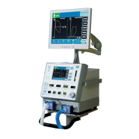
Figure2-2. INVOS™ System (Model 5100C) . . . . . . . . . . . . . . . . . . . . . . . . . . . . . . . . . . . . . . . . . . . . . . . . . . . . . . . . . . . 2-3
Figure3-1. Back Connections and Elements . . . . . . . . . . . . . . . . . . . . . . . . . . . . . . . . . . . . . . . . . . . . . . . . . . . . . . . . . . 3-3
Figure3-2. Side Connections. . . . . . . . . . . . . . . . . . . . . . . . . . . . . . . . . . . . . . . . . . . . . . . . . . . . . . . . . . . . . . . . . . . . . . . . . 3-7
Figure3-3. Preamplifiers, Reusable Sensor Cables, and Sensor Connections. . . . . . . . . . . . . . . . . . . . . . . . . . . 3-8
Figure3-4. Sensor Prep . . . . . . . . . . . . . . . . . . . . . . . . . . . . . . . . . . . . . . . . . . . . . . . . . . . . . . . . . . . . . . . . . . . . . . . . . . . . . 3-10
Figure3-5. Sensor Placement . . . . . . . . . . . . . . . . . . . . . . . . . . . . . . . . . . . . . . . . . . . . . . . . . . . . . . . . . . . . . . . . . . . . . . . 3-11
Figure3-6. OxyAlert NIRSensor Placements: Cerebral, Flank, and Abdominal Shown . . . . . . . . . . . . . . . . . 3-14
Figure4-1. Connecting the Preamplifier to the Monitor . . . . . . . . . . . . . . . . . . . . . . . . . . . . . . . . . . . . . . . . . . . . . . 4-1
Figure4-2. Connecting the Sensor Cable Connectors to the Preamplifier . . . . . . . . . . . . . . . . . . . . . . . . . . . . . 4-2
Figure4-3. Connecting the Sensors to the Sensor Cables. . . . . . . . . . . . . . . . . . . . . . . . . . . . . . . . . . . . . . . . . . . . . 4-2
Figure4-4. Connecting Optional Accessories. . . . . . . . . . . . . . . . . . . . . . . . . . . . . . . . . . . . . . . . . . . . . . . . . . . . . . . . . 4-3
Figure5-1. Welcome Screen . . . . . . . . . . . . . . . . . . . . . . . . . . . . . . . . . . . . . . . . . . . . . . . . . . . . . . . . . . . . . . . . . . . . . . . . . 5-2
Figure5-2. Start Screen, Navigation Bar, Key Panel and Software Version. . . . . . . . . . . . . . . . . . . . . . . . . . . . . . 5-3
Figure5-3. Patient Identifier Screen . . . . . . . . . . . . . . . . . . . . . . . . . . . . . . . . . . . . . . . . . . . . . . . . . . . . . . . . . . . . . . . . . . 5-4
Figure5-4. Main Screen Elements (Two-Channel Monitoring) . . . . . . . . . . . . . . . . . . . . . . . . . . . . . . . . . . . . . . . . 5-5
Figure5-5. Main Screen (Four-Channel Monitoring) . . . . . . . . . . . . . . . . . . . . . . . . . . . . . . . . . . . . . . . . . . . . . . . . . . 5-6
Figure5-6. User Configuration Screen (Page 1) . . . . . . . . . . . . . . . . . . . . . . . . . . . . . . . . . . . . . . . . . . . . . . . . . . . . . . . 5-7
Figure5-7. User Configuration Screen (Page 2) . . . . . . . . . . . . . . . . . . . . . . . . . . . . . . . . . . . . . . . . . . . . . . . . . . . . . . . 5-7
Figure5-8. Event Mark List Screen (OR Event Mark List) . . . . . . . . . . . . . . . . . . . . . . . . . . . . . . . . . . . . . . . . . . . . . . . 5-8
Figure5-9. Event Mark List Screen (ICU Event Mark List) . . . . . . . . . . . . . . . . . . . . . . . . . . . . . . . . . . . . . . . . . . . . . . 5-9
Figure5-10. Event Mark List Screen (Vascular Event Mark List). . . . . . . . . . . . . . . . . . . . . . . . . . . . . . . . . . . . . . . . . . 5-9
Figure5-11. Event Mark List Screen (NICU Event Mark List) . . . . . . . . . . . . . . . . . . . . . . . . . . . . . . . . . . . . . . . . . . . . 5-10
Figure5-12. Baseline Reset Screen. . . . . . . . . . . . . . . . . . . . . . . . . . . . . . . . . . . . . . . . . . . . . . . . . . . . . . . . . . . . . . . . . . . . 5-11
Figure5-13. Channel Inactivity Screen. . . . . . . . . . . . . . . . . . . . . . . . . . . . . . . . . . . . . . . . . . . . . . . . . . . . . . . . . . . . . . . . 5-11
Figure5-14. RS-232 Digital Output Format Selection Screen (Two-Channel Monitoring). . . . . . . . . . . . . . . 5-12
Figure5-15. RS-232 Digital Output Format Selection Screen (Four-Channel Monitoring) . . . . . . . . . . . . . . 5-12
Figure5-16. Tabular Trends Screen—Run Function in Normal Mode. . . . . . . . . . . . . . . . . . . . . . . . . . . . . . . . . . 5-13
Figure5-17. Tabular Trends Screen—Case Archive Function in Normal Mode. . . . . . . . . . . . . . . . . . . . . . . . . 5-13
Figure5-18. Tabular Trends Screen—Manual Set Baseline in Normal Mode . . . . . . . . . . . . . . . . . . . . . . . . . . . 5-14
Figure5-19. Case Archive File List Screen . . . . . . . . . . . . . . . . . . . . . . . . . . . . . . . . . . . . . . . . . . . . . . . . . . . . . . . . . . . . . 5-15
Figure5-20. Trend Graph Screen—Case Archive Function in Normal Mode . . . . . . . . . . . . . . . . . . . . . . . . . . . 5-16
Figure5-21. Trend Graph Screen—Run Function in Normal Mode . . . . . . . . . . . . . . . . . . . . . . . . . . . . . . . . . . . . 5-16
Figure6-1. INVOS™ System in Normal Mode with Low Alarm . . . . . . . . . . . . . . . . . . . . . . . . . . . . . . . . . . . . . . . . . 6-6
Figure6-2. rSO2 Alarm Indicated . . . . . . . . . . . . . . . . . . . . . . . . . . . . . . . . . . . . . . . . . . . . . . . . . . . . . . . . . . . . . . . . . . . . 6-26
Figure6-3. rSO2 Below Baseline . . . . . . . . . . . . . . . . . . . . . . . . . . . . . . . . . . . . . . . . . . . . . . . . . . . . . . . . . . . . . . . . . . . . 6-27
Figure6-4. Technical Alarm Indicated . . . . . . . . . . . . . . . . . . . . . . . . . . . . . . . . . . . . . . . . . . . . . . . . . . . . . . . . . . . . . . . 6-28
Figure7-1. VGA Video Connector Pin-Out . . . . . . . . . . . . . . . . . . . . . . . . . . . . . . . . . . . . . . . . . . . . . . . . . . . . . . . . . . . 7-2
Figure7-2. Digital Output Connector Pin-Out . . . . . . . . . . . . . . . . . . . . . . . . . . . . . . . . . . . . . . . . . . . . . . . . . . . . . . . . 7-8
Figure7-3. Null Modem Cable Diagram for Connection to Digital Output Port. . . . . . . . . . . . . . . . . . . . . . . 7-12
Figure8-1. Two-Channel Start Screen in Database Operational Mode. . . . . . . . . . . . . . . . . . . . . . . . . . . . . . . . . 8-4
Figure8-2. Four-Channel Start Screen in Database Operational Mode . . . . . . . . . . . . . . . . . . . . . . . . . . . . . . . . 8-5
Figure8-3. Main Screen (Four-Channel Monitoring) Database Operational Mode . . . . . . . . . . . . . . . . . . . . . 8-6