98 Technical Specifications Falcon™ 4-CLHS Series
Input Signals Electrical Specifications
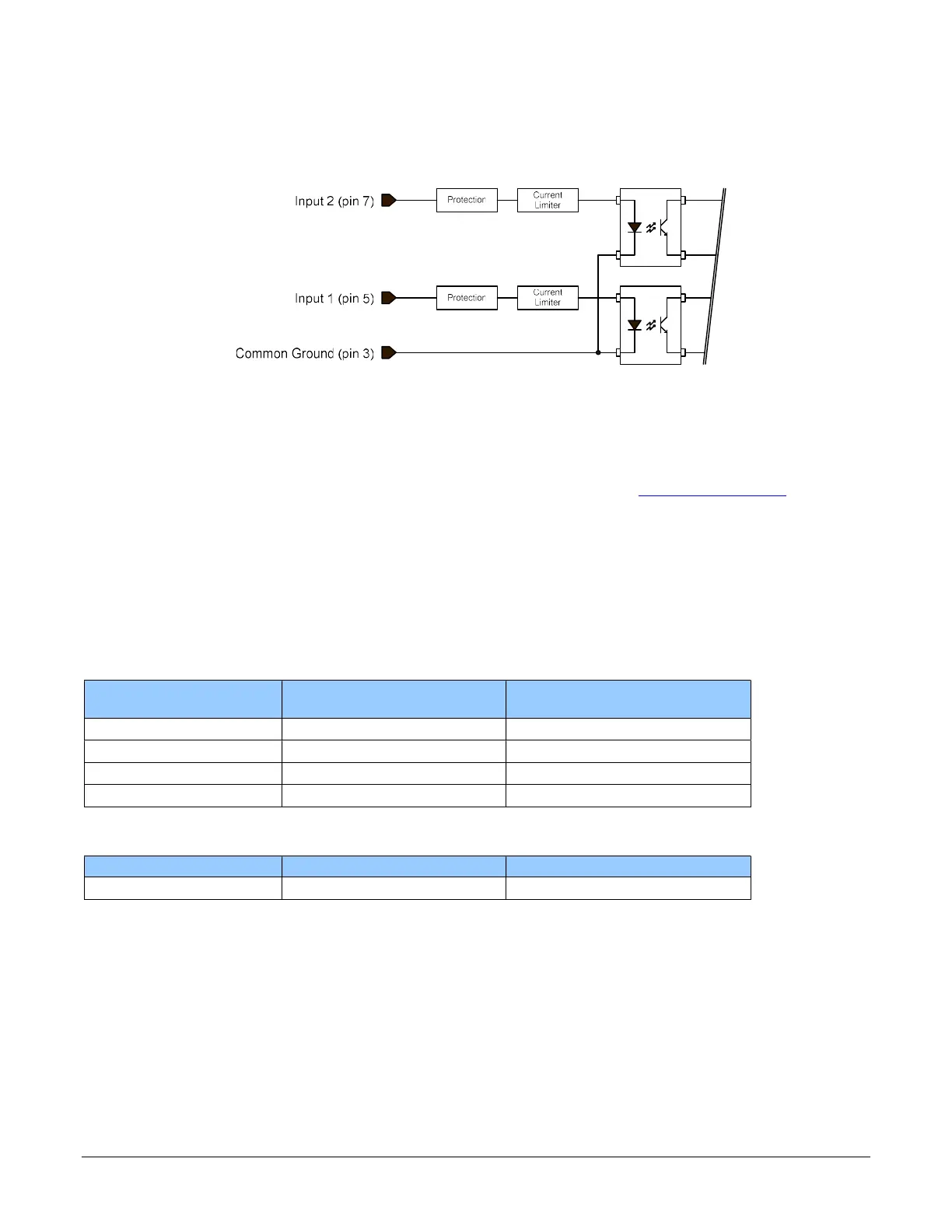
External Inputs Block Diagram
External Input Details
Opto-coupled with internal current limit.
Single input trigger threshold level
(TTL standard: <0.8V=Logical LOW, >2.4V=Logical HIGH. See lineDetectionLevel feature).
Used as trigger acquisition event, counter or timestamp event, or integration control.
User programmable debounce time from 0 to 255µs in 1µs steps.
Source signal requirements:
Single-ended driver meeting TTL, 12V, or 24V standards (see table below)
If using a differential signal driver, only one input can be used due to the shared input
common (see details below)
External Input DC Characteristics
Operating
Specification
Minimum Maximum
Input Voltage +3 V +36 V
Input Current 7 mA 11.8 mA
Input logic Low 0.8 V
Input logic High 2.5 V
Absolute Maximum Range before Possible Device Failure
Absolute Ratings Minimum Maximum
Input Voltage –36 Volts +36 Volts

 Loading...


