52 Operational Reference Falcon™ 4-CLHS Series
Lookup Table (LUT) Overview
The Falcon4-CLHS cameras include a user programmable LUT (lookup table) as a component of its
embedded processing features. A LUT is used for operations such as gamma adjustments, invert
function and threshold processes.
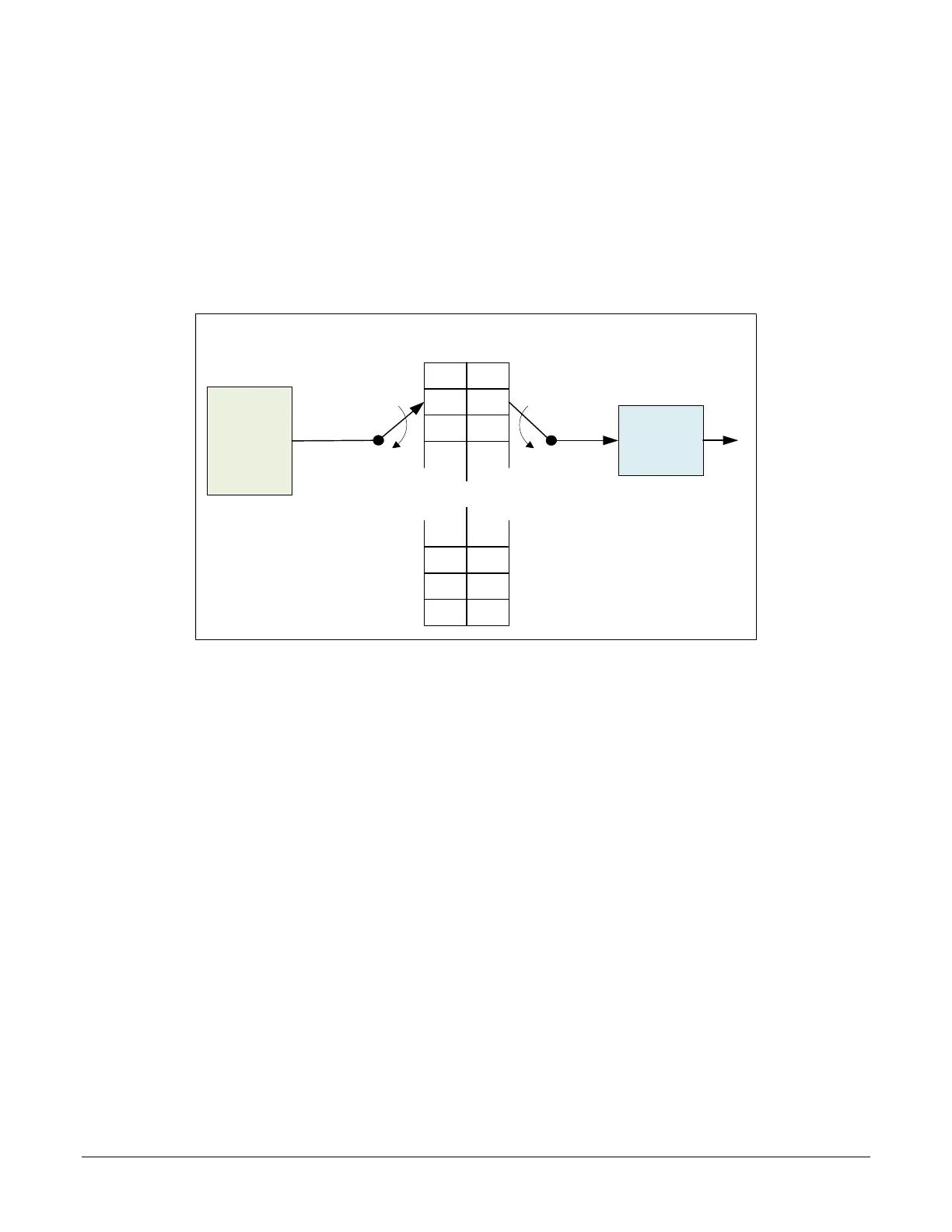
The camera LUT tables are dependent on the sensor (see feature LUT Size) and is illustrated in the
following figure. Pixel data from the sensor is passed through the LUT memory array, where the
new programmed pixel value is then passed to the camera output circuit. The LUT data table is
stored along with other parameters with the user configuration function.
. . .
. . .
0
1
2
3
1020
1023
1022
1021
1023
1022
1021
1020
2
1
0
3
Output
Sensor
Pixel
Data
Simplified LUT Block Diagram
10-bit Input : 10-bit Output
LUT Programmed
as Invert Function
Simplified Example 10-bit to 10-bit LUT Block Diagram
LUT Size vs. Pixel Format
The LUT size will correspond to the camera’s sensor pixel size; for the current Falcon4-CLHS
standard firmware, this is 10 bits per pixel, i.e., 1024. All camera processing is performed at the
10-bit sensor pixel format of the camera, while the end user chooses the pixel format (8-bit or 10-
bit format) to output.
The default neutral LUT programming is as follows:
With Pixel Format = Mono 10, the default LUT data value is equal to the LUT value for each
index. This is a linear LUT that does not modify the sensor data.
With Pixel Format = Mono 8, the LUT remains to be a 10 bit in 10 bit out. The conversion to
8 bit occurs after the LUT.
LUT data is selected as a user file uploaded using the File Access controls. Refer to the Sapera
documentation for information about the SapLut Class. Note that a SapLut file can be uploaded but
cannot be read back.

 Loading...


