102 Technical Specifications Falcon™ 4-CLHS Series
External Output AC Timing Characteristics
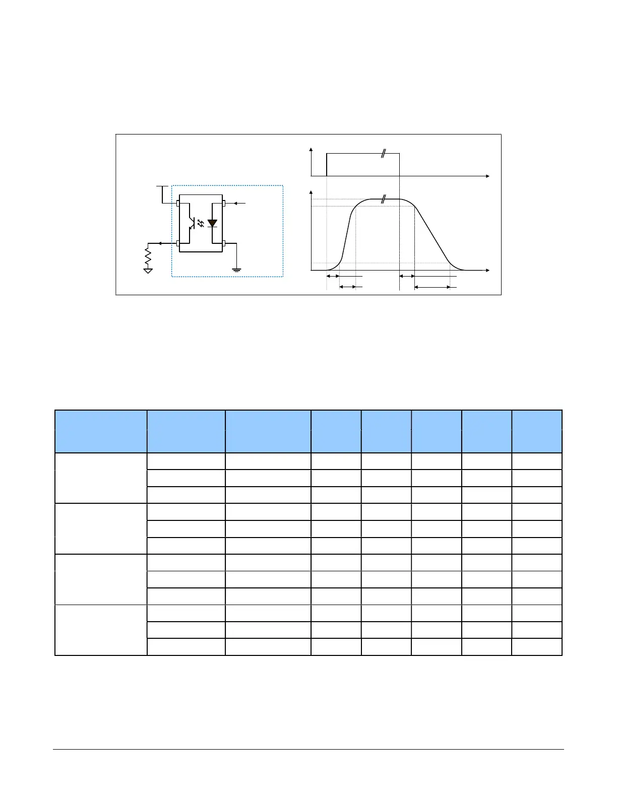
The graphic below defines the test conditions used to measure the Falcon4 external output AC
characteristics, as detailed in the tables that follows.
t
t
Output Control Signal
Output
100%
90%
10%
t
d1
t
rise
t
fa ll
t
d2
Output
Output Common Power
R
Load
Control
Signal
Camera
Output Characteristics, FA-HM00-M4485
Opto-coupled Output: AC Characteristics
Note: All measurements subject to some rounding.
The following tables describes GPO 1 and GPO 2 when the load is connected to a user-provided
ground. Test conditions are with front plate temperature ~60C.
Output Common
Power
Output
R
load
t
d1 (
µs) t
rise (
µs)
t
d2 (
µs) t
fall (
µs)
V
out (
V)
Current
Test (ohm)
Leading
Delay
Rise Time
Trailing
Delay
Fall Time
3V
8 mA 240 0.459 3 11 20.41 2.17
12ma 144 0.6 6.95 4.4 20 1.75
16 mA 40 0.6 11 1 12.9 0.559
5V
8 mA 523 0.469 2.64 12 22 4.24
16 mA 159 0.485 7.52 2.55 12 2.57
24 mA 69 0.64 7.52 1 8.42 1.69
12V
8 mA 1400 0.52 3.28 10.6 25.64 11.23
16 mA 595 0.52 3.28 4.12 13.86 9.61
24 mA 360 0.531 3.76 2.48 13.8 8.72
24V
8 mA 2907 0.541 1.63 22.8 37.8 23.31
16 mA 1346 0.556 2.2 7.4 18.32 21.58
24 mA 861 0.567 2.5 6.61 12.93 20.72

 Loading...


