94 Technical Specifications Falcon™ 4-CLHS Series
Connectors
The Falcon4-CLHS camera has two connectors on its back panel. There is one CLHS (CX4) standard
data and control connector plus a locking 10-pin connector for power and I/O signals. These are
described below.
Camera Link HS (CX4)
The Camera Link HS camera connector (CX4) is defined in the AIA document “Specifications of the
Camera Link HS Interface Standard for Digital Cameras and Frame Grabbers”, which is at version
1.1 at the time of this manual’s writing.
Typically, there is no need to be concerned with the physical pinout of the CX4 connector or cables.
Refer to their site www.visiononline.org for additional information.
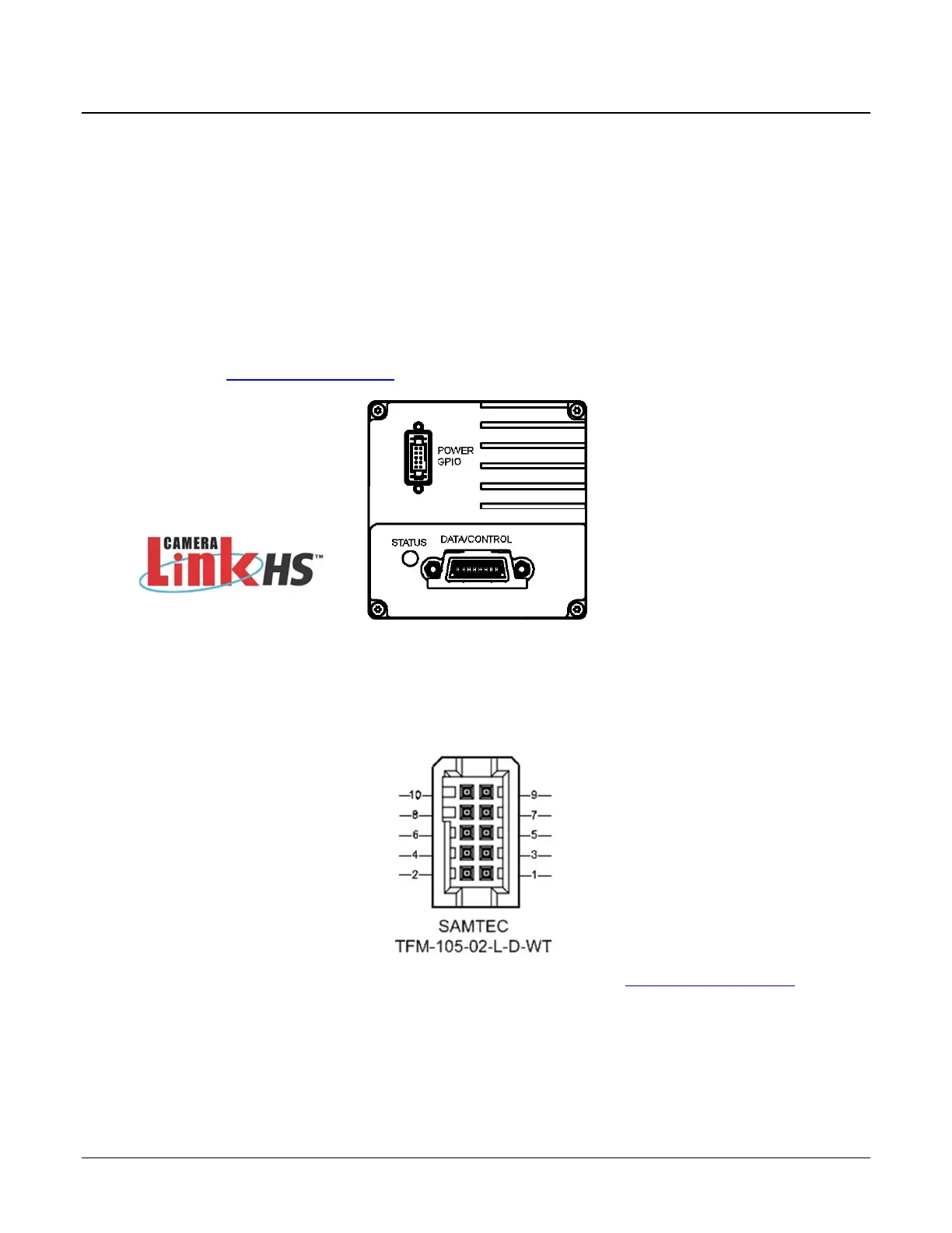
10-pin I/O Connector Details
A DC power source is connected to the 10-pin connector (SAMTEC TFM-105-02-L-D-WT). Falcon4-
CLHS supports connecting cables with retention latches and/or screw locks. The following figure
shows the pin number assignment.
Teledyne DALSA makes available optional I/O cables as described in I/O Cable Accessories. Contact
Sales for availability and pricing.

 Loading...


