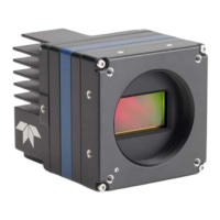
90 Technical Specifications Falcon™ 4-CLHS Series
Technical Specifications
Both 2D and 3D design drawings are available for download from the Teledyne DALSA web site
[https://www.teledynedalsa.com/en/products/imaging/cameras/falcon4-clhs/].
Falcon4-CLHS Identification and Mechanical
Identification Label
Falcon4 cameras have an identification label applied to the bottom side, with the following information:
Model Part Number
Serial number
Calibration date
Barcode
Additional Mechanical Notes
For information on lens requirements see Choosing a Lens with the Correct Image Circle.
Each camera side has two mounting holes in identical locations, which provide good grounding
capabilities.
Overall height or width tolerance is ± 0.05mm.
Temperature Management
Falcon4-CLHS cameras are designed to optimally transfer internal component heat to the outer
metallic body. If the camera is free standing (that is, not mounted) it will be hot to the touch.
Basic heat management is achieved by mounting the camera onto a metal structure via its
mounting screw holes. Heat dissipation is improved by using thermal paste between the camera
body (not the front plate) and the metal structure plus the addition of a heatsink structure.

 Loading...