Falcon™ 4-CLHS Series Operational Reference 37
Output Line Pulse Activation
outputLinePulseActivation Specifies the input line activation mode to trigger the
OutputLine pulse.
1.00
Beginner
DFNC
Rising Edge RisingEdge
Specifies that the trigger is considered valid on the
rising edge of the source signal.
Falling Edge FallingEdge Specifies that the trigger is considered valid on the
falling edge of the source signal.
Any Edge AnyEdge Specifies that the trigger is considered valid on the
falling or rising edge of the source signal.
Output Line Pulse Delay outputLinePulseDelay Sets the delay (µs) before the output line pulse
duration signal.
1.00
DFNC
Beginner
Output Pulse Duration outputLinePulseDuration Sets the width (duration) of the output line pulse in
microseconds (µs).
1.00
DFNC
Beginner
Output Line Value outputLineValue Set the GPIO out value when outputLineSource is
SoftwareControlled.
1.00
DFNC
Expert
Low Low Output line is low
High High Output line is high
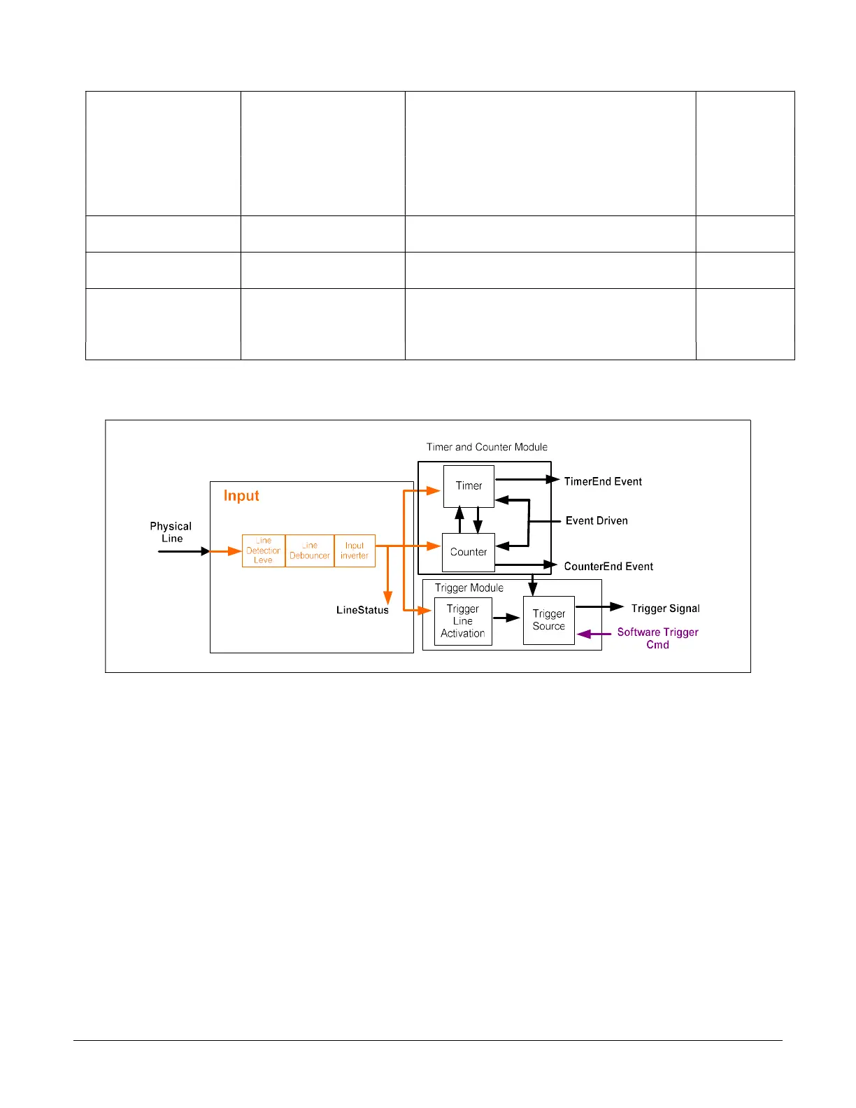
I/O Module Block Diagram

 Loading...


