Xtium-CL MX4 User's Manual Technical Specifications • 99
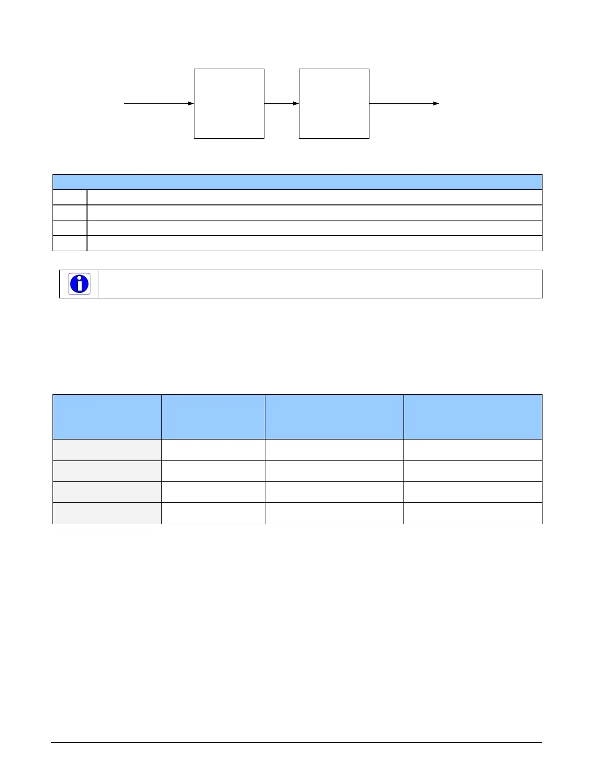
Trigger Signal Total Delay
Opto-Coupler
t(oc)
Debouncer
t(d)
External Trigger
t(et)
Validated Trigger
t(vt) = t(et) + t(oc) + t(d)
Figure 28: External Trigger Input Validation & Delay
External Trigger Timing Specifications
t(et) time of external trigger in µs
t(oc) time opto-coupler takes to change state (time varies dependent on input voltage)
t(d) user set debounce duration from 1 to 255µs
t(vt) time of validated trigger in µs
Note: Teledyne DALSA recommends using the fastest transition to minimize the time it takes for
the opto-coupler to change state.
If the duration of the external trigger is > t(oc) + t(d), then a valid acquisition trigger is detected.
It is possible to emulate an external trigger using the software trigger which is generated by a
function call from an application.
The following table provides the input switching points and propagation delay details.
Trigger Level Switch Point Propagation Delay
t(oc)
(rising edge signal ↑ )
Propagation Delay
t(oc)
(falling edge signal ↓ )
RS-422
1.6V 1.75 µs 5.5 µs
TTL
1.6V
1.75 µs 5.5 µs
12V
6V 2.6 µs 2.6 µs
24V
12V
1.9 µs 3.1 µs