Xtium-CL MX4 User's Manual Technical Specifications • 101
J1/J4: External Signals
Connectors
Reserved
Reserved
4
External Signals
Xtium-CL MX4 rev. A1
26
27
:
:
V (+)
3
V (+)
Compatible
Driver
Compatible
Driver
2
V
(+)
Compatible
Driver
1
V (+)
Compatible
Driver
General Input Signal Common /
Input 1 (-)
Reserved25 :
Reserved
24 :
Reserved23
:
General Output 422 :
General Output
321 :
Reserved
Reserved
19
20
:
:
Reserved18 :
Reserved17 :
General Input 416 :
General Input 315 :
Power (12 Volts
)14 :
Ground13
:
General Output 2 / Strobe 212 :
General Output
1 /
Strobe
111 :
Ground10 :
General Input 2 / Trigger 29 :
General Input 1 / Trigger
1
(+)8 :
General Input Common7 :
Shaft Encoder B (+)6 :
Shaft Encoder B (-)5 :
Ground
4
:
Shaft Encoder A (+)3 :
Shaft Encoder A
(
-
)
2 :
Ground1 :
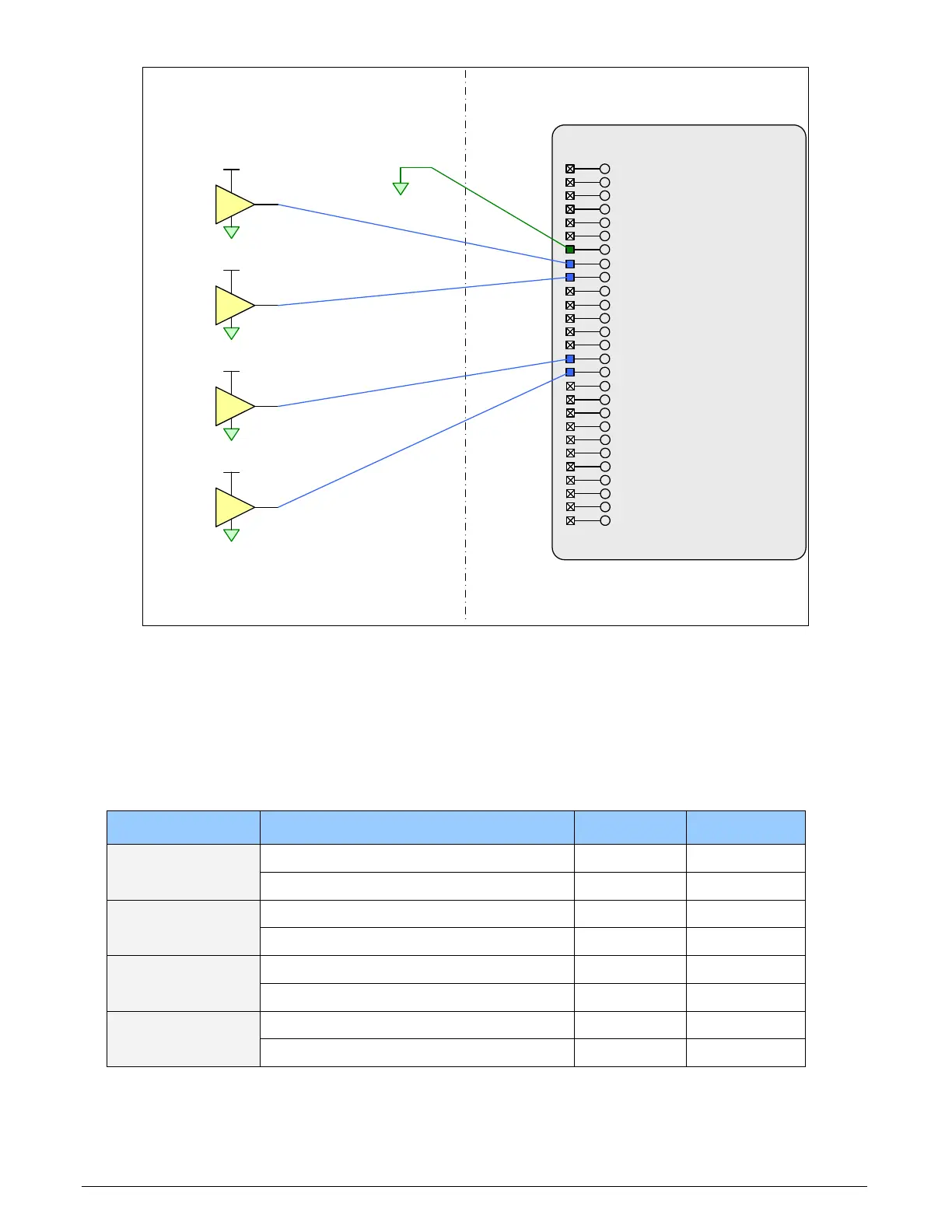
Figure 30:Rev A1: External Signals Connection Diagram
External Driver Electrical Requirements
The Xtium-CL allows user selected (software programmable) input switching points to support
differential (RS-422) input signals and single ended (TTL, 12V, 24V) input signals. The following
table defines the external signal voltage requirements from the driver circuits connected to the
Xtium external inputs.
Input Level Description MIN MAX
RS-422
Output Voltage High (V
OH
)
2.4 V 13.0 V
Output Voltage Low (V
OL
)
-2.4 V -13.0 V
TTL
Output Voltage High (V
OH
)
2.4 V 5.5 V
Output Voltage Low (V
OL
)
0 V 0.8 V
12V
Output Voltage High (V
OH
)
9 V 13.2 V
Output Voltage Low (V
OL
)
0 V 3 V
24V
Output Voltage High (V
OH
)
18 V 26.4 V
Output Voltage Low (V
OL
)
0 V 6 V