102 • Technical Specifications Xtium-CL MX4 User's Manual
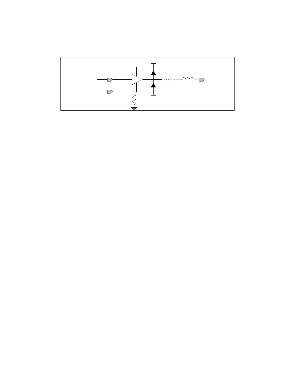
Note 2: General Outputs /Strobe Output Specifications
Each of the eight General Outputs are TTL (3.3V) compatible. General Output 1 and 2 also function
as the Strobe Output 1 and 2 respectively controlled by Sapera strobe control functions. See
“Board Information” user settings. The following figure is typical for each General Output.
75Ω
Buffer
LVTTL
To User
Interface
Connector
3.3V
Output
Enable
EMI
Filter
Figure 31: General Outputs Electrical Diagram
Output Details:
• Each output has a 75-ohm series resistor
• The 2 diodes protects the LVTTL buffer against overvoltage
• Each output is a tri-state driver, enabled by software
• Minimum guaranteed output current is +/- 24mA @ 3.3V
• Maximum output current is 50mA
• Maximum short circuit output current is 44mA
• Minimum voltage for output level high is 2.4V, while maximum voltage for output low is 0.55V
• Maximum output switching frequency is limited by driver and register access on the PCIe bus.
For Strobe Usage:
• Refer to Sapera Strobe Methods parameters:
CORACQ_PRM_STROBE_ENABLE
CORACQ_PRM_STROBE_POLARITY
CORACQ_PRM_STROBE_LEVEL
CORACQ_PRM_STROBE_METHOD
CORACQ_PRM_STROBE_DELAY
CORACQ_PRM_STROBE_DURATION
• See also *.cvi file entries:
Strobe Enable, Strobe Polarity, Strobe Level, Strobe Method, Strobe Delay, Strobe Duration.