Xtium-CL MX4 User's Manual Technical Specifications • 91
Connector and Switch Specifications
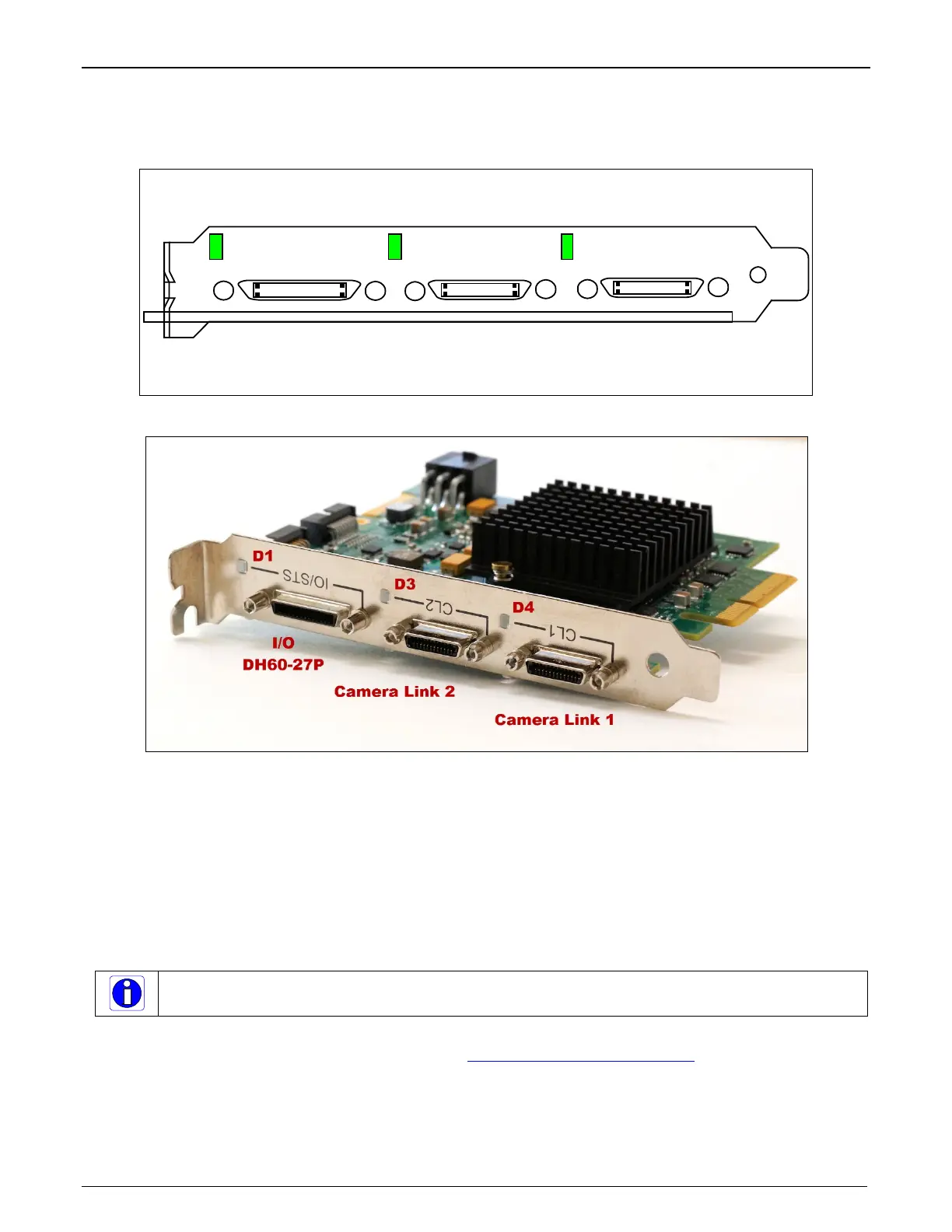
Xtium-CL MX4 End Bracket Detail
Camera Link 2
LED/connector
Xtium-CL MX4
Camera Link 1
LED/connector
I/O – DH60-27P
female connector
Board
Status
LED
Figure 25: End Bracket Details
The hardware installation process is completed with the connection of a supported camera to the
Xtium-CL MX4 board using Camera Link cables (see Camera Link Cable).
• The Xtium-CL MX4 board supports a camera with one or two Camera Link connectors (one
Base, one Medium or one Full – see Data Port Summary for information on Camera Link
configurations).
• Connect the camera to the J3 connector with a Camera Link cable. When using a Medium or
Full camera, connect the second camera connector to J2.
Note: If the camera is powered by the Xtium-CL MX4, refer to J7: Power Connector for power
connections.
Contact Teledyne DALSA or browse our web site www.teledynedalsa.com/mv
for information on
Xtium-CL MX4 supported cameras.