Xtium-CL MX4 User's Manual Xtium-CL MX4 Reference • 57
Virtual Frame Trigger for Line Scan Cameras
When using line scan cameras, a frame buffer is allocated in host system memory to store
captured video lines. To control when a video line is stored as the first line in this “virtual” frame
buffer, an external frame trigger signal is used.
For fixed length frames, the Sapera vertical cropping parameter controls the number of lines
sequentially grabbed and stored in the virtual frame buffer.
For variable length frames, the External Frame Trigger (when a level or dual input type is
selected) controls the number of lines sequentially grabbed up to the maximum of lines in the
virtual frame buffer.
For both fixed and variable length frames, choosing an active low/high or dual input permits
grabbing multiple consecutive images as long as the chosen signal is active. This action is also
called “rolling over” to the next buffer. When choosing a single rising or falling edge, a single frame
will be acquired, there is never any roll over.
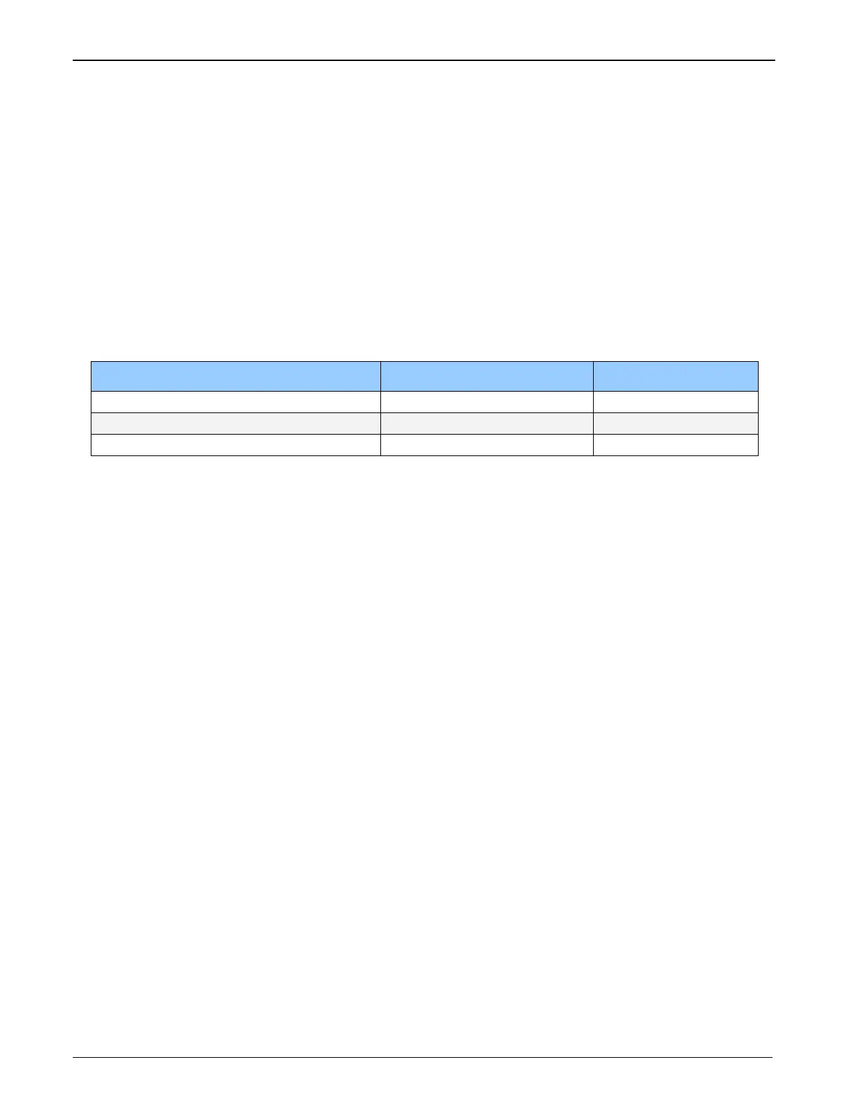
External Frame Trigger Detection Fixed Frame Variable Frame
Active Low/High Roll Over Roll Over
Rising/Falling Edge No Roll Over No Roll Over
Dual Input Rising/Falling Edge Roll Over Roll Over
Virtual Frame Trigger Timing Diagrams
The following timing diagrams show the use of a virtual frame trigger to define when an image line
is stored at the beginning of the virtual frame buffer. The virtual frame trigger signal (generated by
some external event) connects to the Xtium-CL MX4 trigger input.
Virtual frame trigger can be differential (RS-422) or single ended (TTL, 12V, 24V) industry
standard, and be rising or falling edge active, active high or low, or double pulse rising or falling
edge.
Virtual frame trigger connects to the Xtium-CL MX4 via the External Trigger Input 1 & 2 inputs.
• Trigger Input #1 on connector J1: pin 8
• Trigger Input #2 on connector J1: pin 9
The Sapera vertical cropping parameter specifies the number of lines captured (maximum size
of virtual frame).
Synchronization Signals for a 10 Line Virtual Frame
The following timing diagram shows an example of grabbing 10 image lines from a line scan
camera and the use of a virtual frame trigger to define when a video line is stored at the beginning
of the virtual frame buffer.
In this example, virtual frame trigger control is configured for rising edge trigger.
Camera control signals are active at all times. These continually trigger the camera acquisition
in order to avoid corrupted video lines at the beginning of a virtual frame.
The camera control signals are either timing controls on Xtium-CL MX4 shaft encoder inputs, or
line triggers generated internally by the Xtium-CL MX4.
The following timing diagram shows the relationship between External Frame Trigger input,
External Shaft Encoder input (one phase used with the second terminated), and camera control
output to the camera.