52 • Xtium-CL MX4 Reference Xtium-CL MX4 User's Manual
Xtium-CL Flow Diagram
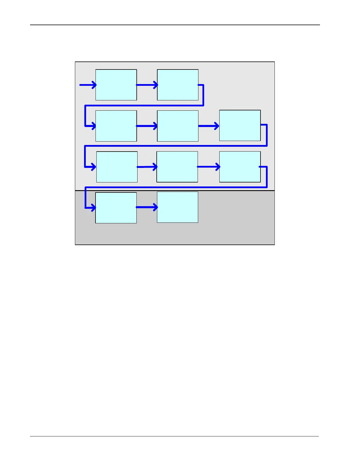
The following diagram represents the sequence in which the camera data acquired is processed
through the Xtium-CL.
Camera
Link
Front-End
Image
Buffer
FFC/FLC
Cropper (Fine
)
Host
DMA
ACU
-
Plus
DTE
Horizontal Flip
Look Up Table
White-Balance
Gain (RGB
Pixels)
Cropper
(Coarse)
Color
Conversion
(Bayer)
Figure 13: Xtium-CL MX4 Flow Diagram
Camera Link Front End: Extracts the clock, LVAL, FVAL and data from the Camera Link ports
based on the Camera Link configuration selected.
Image Buffer: Stores the video data using the model of video frames.
Cropper (Coarse): Horizontal cropper used when reading out from the memory.
Color Conversion: When enabled for particular cameras, converts Bayer and Bi-Color video
data into RGB data.
White Balance Gain: Applies White Balance Gain to RGB data.
FFC/FLC: Flat Field/Flat Line correction. Applies to Monochrome data only.
Lookup Tables: Applies lookup table transformation to the data going to the host memory.
Horizontal Flip: Performs the line data flip process.
Cropper (Fine): Crops the resulting image when used, using a 4-byte resolution.
Host DMA: Transfers the data from frame grabber into the host buffer memory. This module
will also perform the vertical flip if enabled.