Xtium-CL MX4 User's Manual Technical Specifications • 105
Note 3: RS-422 Shaft Encoder Input Specifications
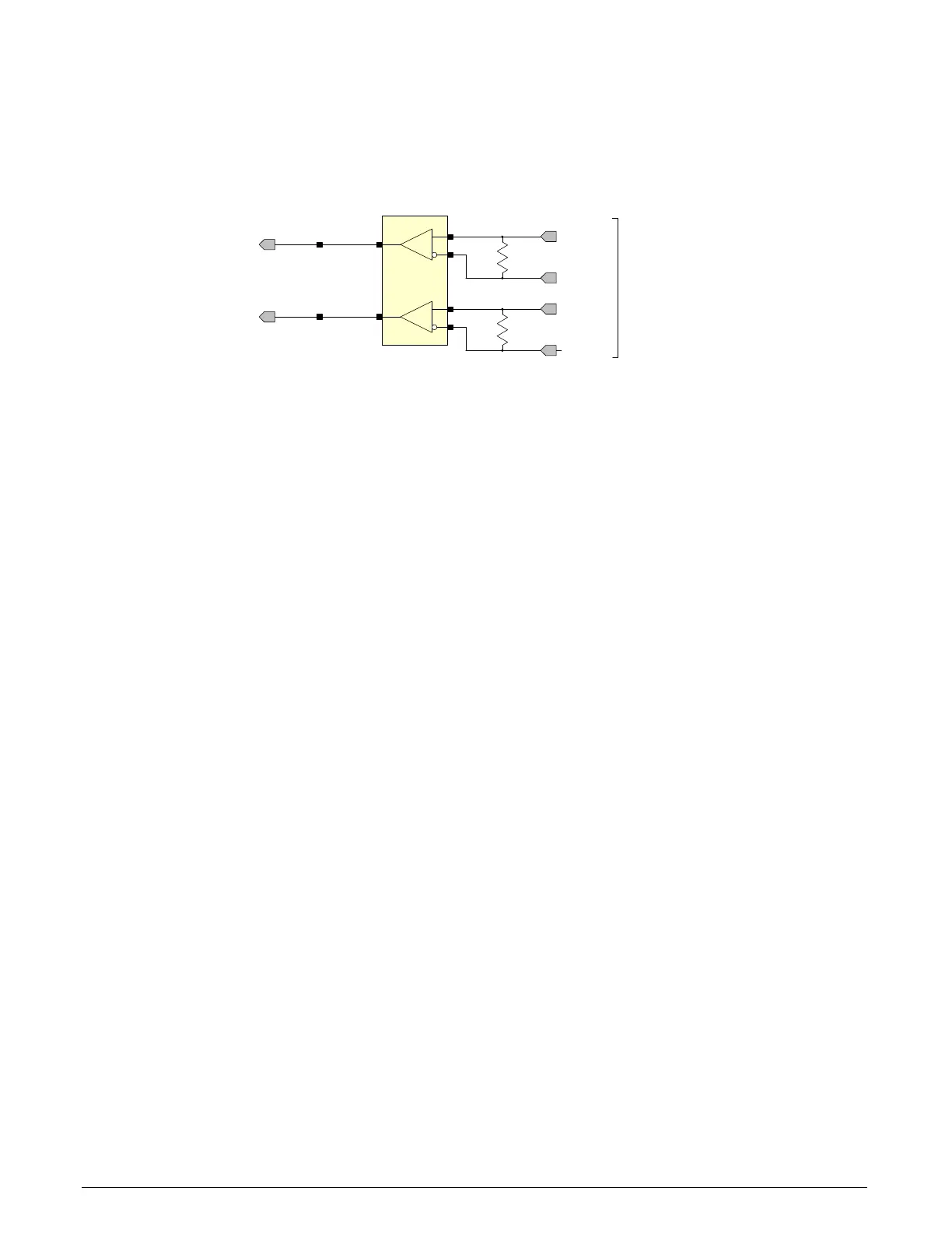
Dual Quadrature Shaft Encoder Inputs (phase A and phase B) connect to differential signals
(RS-422) or single ended signals. The figure below shows the simplified representation of these
inputs.
From User
Interface
Connector
100Ω
PhaseB+
PhaseB-
100Ω
PhaseA+
PhaseA-
Phase B
Phase A
Figure 34: RS-422 Shaft Encoder Input Electrical Diagram
• RS-422 differential line receiver used is am26lv32.
• Input signals must meet the following
• Maximum differential input voltage is +/- 7V.
• Minimum differential voltage level is +/- 200mV.
• Both inputs have a 100-ohm differential resistor.
• Maximum input signal frequency is 10 MHz.
• The Xtium-CL provides ESD filtering on-board.
• See Line Trigger Source Selection for Line scan Applications for more information.
• Refer to Sapera parameters:
CORACQ_PRM_SHAFT_ENCODER_ENABLE CORACQ_PRM_SHAFT_ENCODER_DROP
or refer to CORACQ_PRM_EXT_LINE_TRIGGER_ENABLE
CORACQ_PRM_EXT_LINE_TRIGGER_DETECTION
CORACQ_PRM_EXT_LINE_TRIGGER_LEVEL (fixed at RS-422)
CORACQ_PRM_EXT_LINE_TRIGGER_SOURCE
• See also *.cvi file entries:
Shaft Encoder Enable, Shaft Encoder Pulse Drop,
or see External Line Trigger Enable, External Line Trigger Detection, External Line Trigger Level,
External Line Trigger Source.
• For TTL single ended signals, connect a bias voltage to the RS-422 (-) input to ensure correct
detection of the logic state of the signal connected to the RS-422 (+) input. See the following
section for connection methods.