Xtium-CL MX4 User's Manual Technical Specifications • 107
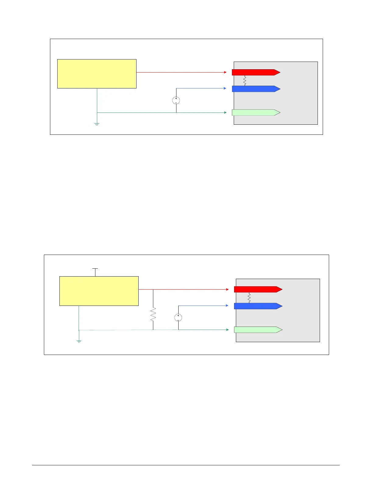
Note 3.2: Interfacing to a TTL (also called Push-Pull) Output
RS
-422
(+) input
RS
-422
(-
)
input
FG/system GND
DC
Bias Voltage
+2
V
GND
Frame Grabber System
Interfacing
TTL Output to RS-422 Inputs
via a Line Buffer/
Driver
TTL signal source
& Buffer Driver
(example: 74ACT244)
100
ohm
Figure 36: Interfacing TTL to RS-422 Shaft Encoder Inputs
• The graphic shows a single-ended driver signal interfaced to the RS-422 input.
• RS-422 (-) input is biased to a DC voltage of +2 volts.
• This guarantees that the TTL signal connected to the RS-422 (+) input will be detected as a
logic high or low relative to the (-) input.
• The TTL shaft encoder ground, the bias voltage ground, and the Xtium-CL MX4 computer
system ground must be connected together.
• DC voltage for the RS-422 (-) input can be generated by a resister voltage divider.
• Use a single battery cell if this is more suitable to your system.
Note 3.3: Interfacing to a Line Driver (also called Open Emitter) Output
RS-
422 (+) input
RS-
422 (-)
input
FG/system GND
DC
Bias Voltage
Vcc/
2
GND
Frame Grabber System
Interfacing Line Driver/Open Emitter Output to RS-422
Inputs
Generic Line Driver/Open Emitter
Output
Vcc
Pull-down resistor needed if it is not
already present in the Shaft Encoder.
Value depends on the characteristics
of the Shaft Encoder Output
100 ohm