110 • Technical Specifications Xtium-CL MX4 User's Manual
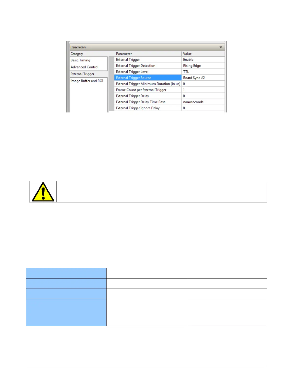
The Sync Slave Xtium board is configured to receive its trigger on the board sync signal. As
an example the following image shows the Xtium board configured for an external sync on
board sync #2.
Test Setup: Start the acquisition on all slave boards. The acquisition process is now waiting for
the control signal from the master board. Trigger master board acquisition and the acquisition
start signal is sent to each slave board.
J7: Power Connector
DC Power Details
Warning: Never remove or install any hardware component with the computer power on.
Never connect a power cable to J7 when the computer is powered on.
• Connect a computer 6-pin PCI Express power connector to J7 to supply DC power to the
Camera Link connectors for PoCL operation and/or to supply power to connector J1. Older
computers may need a power cable adapter (see Power Cable Assembly OR-YXCC-PWRY00).
• The 12 Volt can supply up to 8W of power to the cameras (4W per connector) and 6W to J1 or
J4. Note that J1 and J4 have a 500 mA re-settable fuse on the board. If the fuse trips open,
turn off the host computer power. When the computer is powered again, the fuse is
automatically reset.
Differences between Rev A1 and Rev A2
Board Revision
A1 A2
User Interface Outputs
4 8
Power on J1/J4
12V 5V and 12V
User Interface Inputs
1 differential (LVDS/RS-422)
/Single Ended
+
3 Single Ended
4 differential (LVDS/RS-422),
Single Ended