90 • Technical Specifications Xtium-CL MX4 User's Manual
Connector and Switch Locations
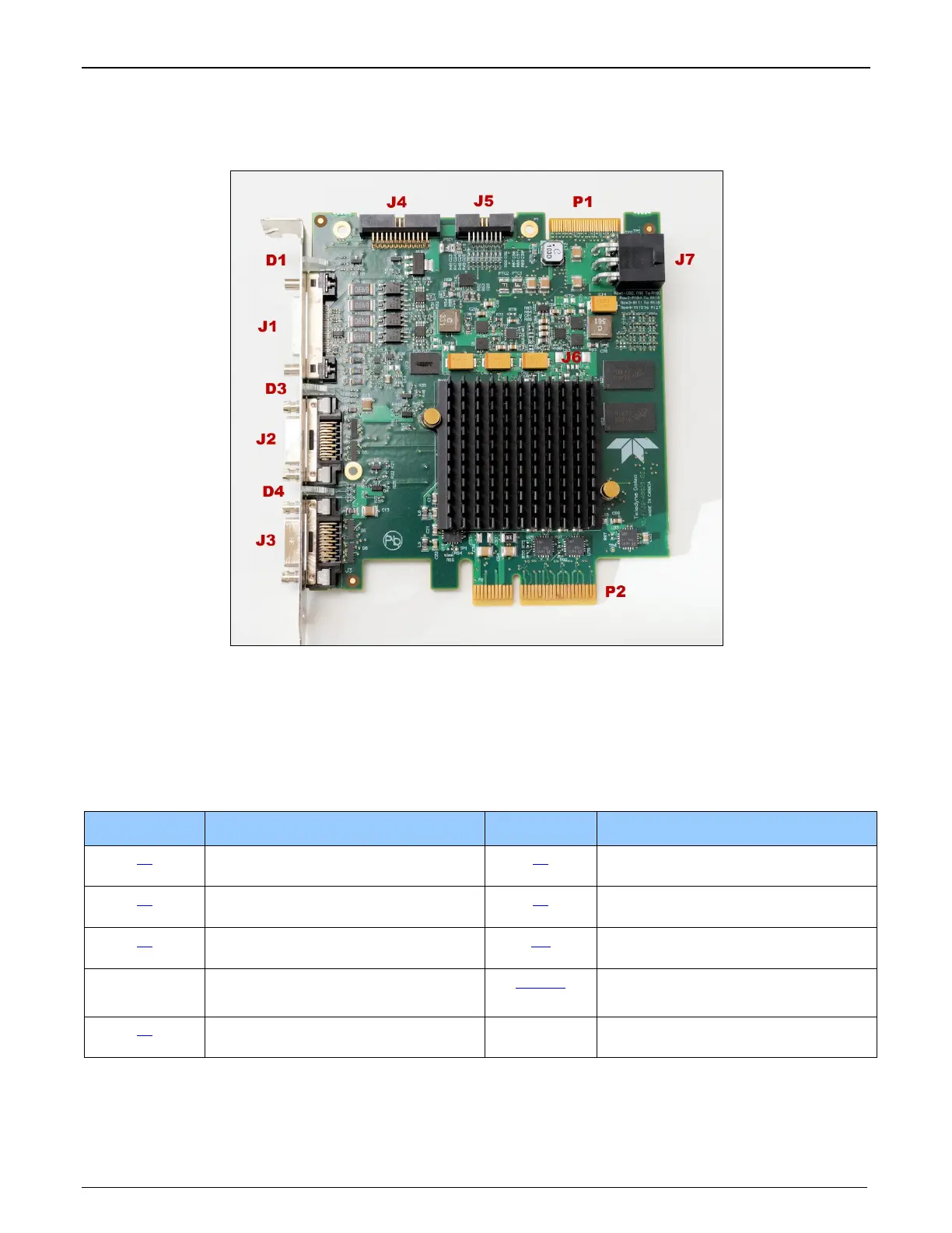
Xtium-CL MX4 Board Layout Drawing
Figure 24: Board Layout
Connector / LED Description List
The following table lists components on the Xtium-CL MX4 board. Detailed information concerning
the connectors/LEDs follows this summary table.
Location Description Location Description
J1
External Signals connector
DH60-27P
J5
Multi Board Sync
J2 Camera Link 2 Connector J7
PC power to camera interface
and/or J1
J3 Camera Link 1 Connector D1
Boot-up/PCIe Status LED
(refer to text)
P2
PCIe x4 computer bus connector
(Gen2 compliant slot preferred)
D3, D4
Camera status LEDs
J4
Internal I/O Signals connector
(26-pin SHF-113-01-L-D-RA)
J6, P1 Reserved