INTRODUCTION
5
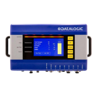
SC5100 CONTROLLER
System Signal LEDs
System Event LEDs
Ethernet Status LEDs
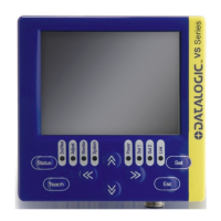
KEYPAD AND DISPLAY
The SC5100 display shows different messages according to the following operating
modes. Use the SC5100 keypad to scroll through the windows or navigate in the menu.
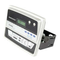
Name Colors State Function
1 POWER
BLUE
RED
BLUE
RED
OFF
SC5100 Properly Powered
Polarity on Power Reversed
No Power Connected
2 TRIG GREEN
ON
OFF
Photoelectric Sensor Active
Photelectric Sensor Not Active
3 SW TRIG GREEN
ON
OFF
Software Trigger Acknowledge Active
Software Trigger Acknowledge Not Active
4 TACH GREEN
BLINKING
OFF for extended period
Encoder Active
Encoder Inactive
Name Colors State Function
5 STATUS
GREEN
RED
YELLOW
GREEN
RED
YELLOW
Controller Status OK
Scanner Cluster Failure
Warning
Name Colors State Function
6 &
7
SYNC OUT
SYNC IN
GREEN
AMBER
Blinking Green and Amber
Blinking Amber
Off
Ethernet Port Activity 100 MBps Speed
Ether Port Activity 10 Mbps Speed
No Ethernet Connection
8 &
9
EBC 1 & 2 GREEN
Blinking Green and Amber
Blinking Amber
Off
Ethernet Port Activity 100 Mbps Speed
Ethernet Port Activity 10 Mbps Speed
No Ethernet Connection
10-
13
ETH 1 - 4 GREEN
Blinking Green
Blinking Amber
Blinking Green and Amber
Off
Ethernet Port Activity 1 Gbps Speed
Ethernet Port Activity 100 Mbps Speed
Ether Port Activity 10 Mbps Speed
No Ethernet Connection
Symbols Meaning
Menu Menu
Up Scroll Up
Down Scroll Down
Enter Enter
Clear Clear