ELECTRICAL INSTALLATION
31
SC5100 CONTROLLER
Insulation on individual wires should be removed to expose 13 mm [0.5 in] of bare
metal before inserting into the pin block.
Selecting the Correct CBX Connection Box for Your Application
Typical applications require a single CBX connection box to connect the trigger and
encoder inputs to the controller. The SC5100 controller sources power to these devices.
Other possible CBX connections are for digital outputs or a serial host. The CBX100 and-
CBX510 each provide different input and output signals. Applications Engineering and
you will select the correct box based on the needs of your application.
SC5100 TO CBX CONNECTIONS
Two ports are available for attaching to CBX connection boxes. The wiring for these two
ports is illustrated below.
NOTE: WB CONN must be connected to GND on each CBX Port for V+ to be
active In1.
In2 is used for Trigger and Encoder respectively on CBX1 only.
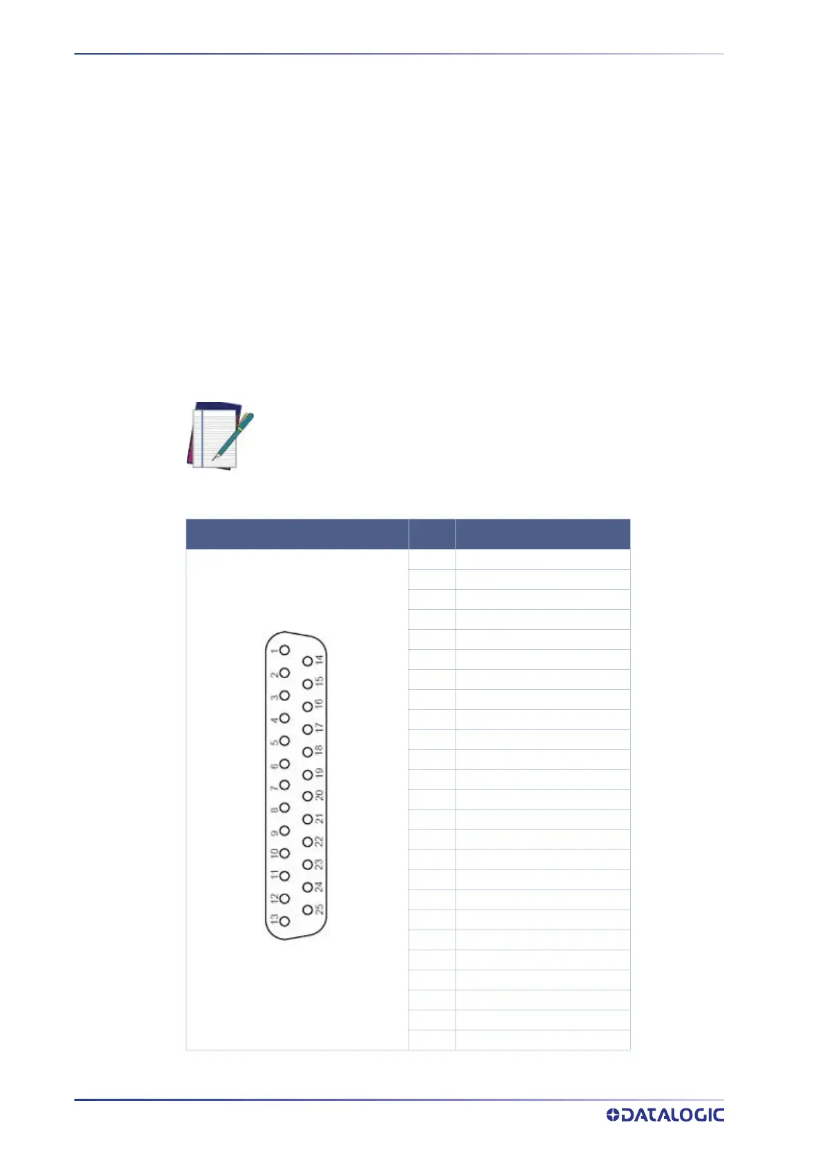
25P D SUB CONNECTOR
PIN SIGNAL
1 Chassis GND
2 Main TX/TX+
3 Main RX/RX+
4 Main RTS/TX-
5 Main CTS/RX-
6 In2+ (Encoder+ on CBX1)
7 Main Serial SGND
8 Out1+
9 IO4+
10 In2- (Encoder-on CBX1)
11 Out2+
12 Out2-
13 V+
14 In3+
15 IO4-
16 Out3+
17 Out3-
18 In1+ (Trigger+ on CBX1)
19 In1- (Trigger- on CBX1)
20 Aux Serial RX
21 Aux Serial TX
22 Out1-
23 WB CONN
24 In3-
25 GND