ELECTRICAL INSTALLATION
25
SC5100 CONTROLLER
SC5100 Electrical Connections
After completing mechanical installation, use this section to properly connect your
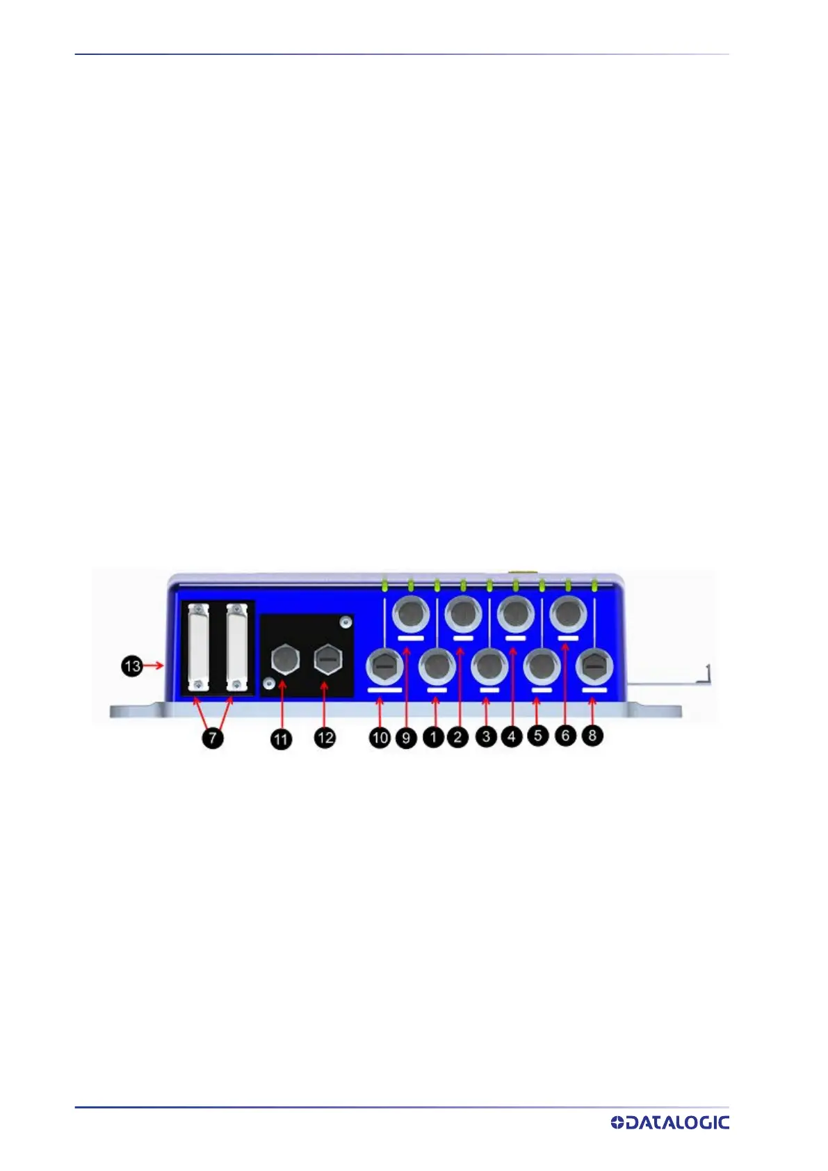
SC5100 controller model to the necessary devices:
1. EBC1 - Possible Laser Scanner (M12 4 pole female D Coded)
2. EBC2 - Possible Laser Scanner (M12 4 pole female D Coded)
3. ETH1 - Host Gigabit Ethernet-Default Host (M12 8 pole female A Coded)
4. ETH2 - Ethernet Gigabit Ethernet-Default Aux (M12 8 pole female A Coded)
5. ETH3 - Ethernet Gigabit Ethernet-Default Aux (M12 8 pole female A Coded)
6. ETH4 - CFG Gigabit Ethernet-Default Config (M12 8 pole female A Coded)
7. I/O 1 & 2 - to CBX’s (25 Pin DSUB female)
8. POWER (M12 5 pole male A Coded)
9. SYNC IN - SC5100 or AV500/AV900 Camera in (M12 8 pole female A coded)
10. SYNC OUT - SC5100 or AV500/AV900 Camera out (M12 8 pole male A coded)
11. PROFIBUS or PROFINET if available. Profinet models port X1.P2
12. PROFIBUS or PROFINET if available. Profinet models port X1.P1
13. USB - General USB A 2.0 connections
Connecting a PC to the SC5100
During initial setup a PC or laptop may be connected to the SC5100. Connect an Ether-
net cable to Ethernet 4, the default Configuration port of the SC5100, to your PC Ether-
net port. For more information on using and connecting to e-Genius, see on-line help.
The default IP Address for the Configuration Port is 192.168.3.100.


 To Next Page