ELECTRICAL INSTALLATION
33
SC5100 CONTROLLER
Photoelectric Sensor Connections to CBX510
Barcode scanning applications often use a Datalogic photoelectric sensor as a trigger
device. The photoelectric sensor is wired directly into the CBX510 terminal block. If your
application uses a trigger other than the one specified by Datalogic, follow the appropri-
ate wiring diagram.
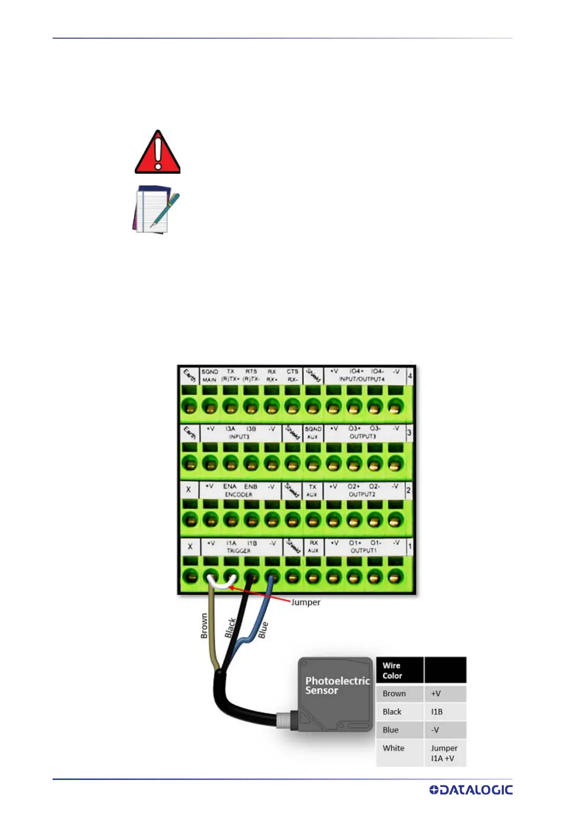
The following diagrams illustrate standard recommended wiring of the Photoelectric
Sensor to the CBX510 terminal block.
Photoelectric Sensor to CBX510 (NPN)
The following diagram illustrates standard recommended wiring of the Photoelectric
NPN sensor in an SC5100 application to the CBX510.
WARNING: You must use shielded interface cables with this product. To
maintain FCC compliance the cable shield must make a 360 degree connec-
tion to the shielded mating connector.
NOTE: To confirm the photoelectric sensor is functioning properly, watch
the TRIGGER LED first in the CBX and then on the controller while the pho-
toelectric sensor’s beam is blocked. The Datalogic photoelectric sensor
also includes a status LED.