CONNECTING AN SC5100 CONTROLLER
PRODUCT REFERENCE GUIDE
28
Ethernet Interface
Two standard EBC M12 4 pole D-Coded female connectors are provided on the SC5100
for Ethernet connections, labeled EBC1 and EBC2. These are reserved for building EBC
clusters, typically cluster members are DS8110 and DX8210 scanners. This interface is
IEEE 802.3 10 BaseT and IEEE 902.3u 100 Base Tx compliant.
Gigabit Ethernet
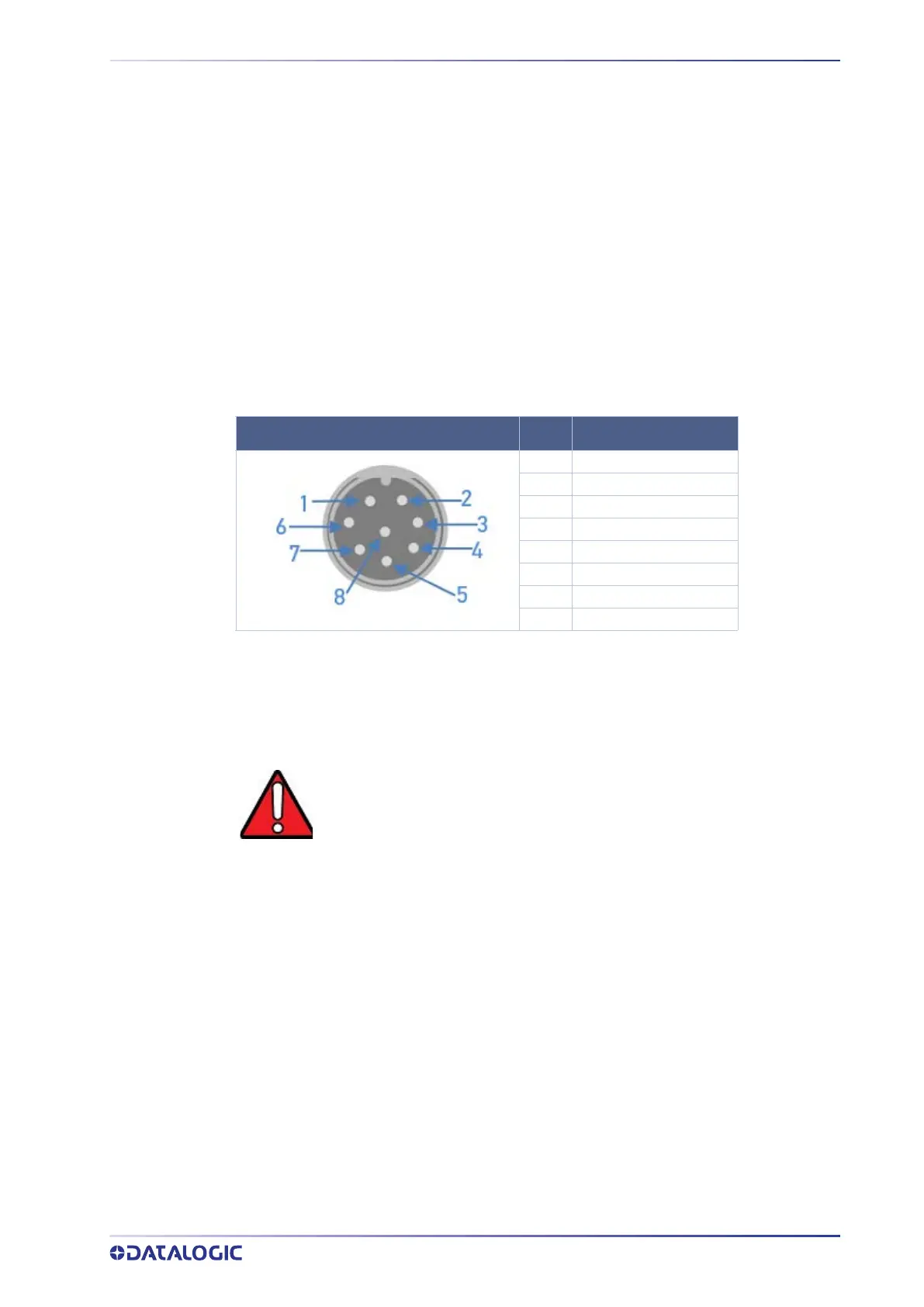
Four standard Ethernet M12 8-pin A-Coded female connectors are provided on the
SC5100's upper cover for the Ethernet Connections: ETH1, ETH2, ETH3, and ETH4 are
used as general purpose Gigabit Ethernet ports which can be used for Host connection
as well as connecting other Ethernet accessories (Scale, DC3000, WebSentinel, etc.). Ïhis
interface is IEEE 802.3ab 1000BASE-T, IEEE 802.3u 100BASE-TX, and IEEE 802.3az
10BASE-Te compliant. (See attachment for figure to the right)
SD Card Slot
Open the access panel to view the external SD Card slot which is used for storing the
SC5100 software and configuration. The slot supports a standard size SD card.
To remove the SD card, push in on the card until a click is heard. The card can then be
pulled out. To reinstall, push in on the card until a click is heard and replace the USB/SD
panel cover. Take extra care to follow safety procedures to avoid ESD damage to the
exposed connections under the USB/SD panel on the side of the SC5100.
M12 8P A CODED FEMALE
PIN SIGNAL
1 Data_3-
2 Data_4+
3 Data_4-
4 Data_1-
5 Data_2+
6 Data_1+
7 Data_3+
8 Data_2-
WARNING: Disconnect power to the SC5100 before removing the SD Card.