ELECTRICAL INSTALLATION
41
SC5100 CONTROLLER
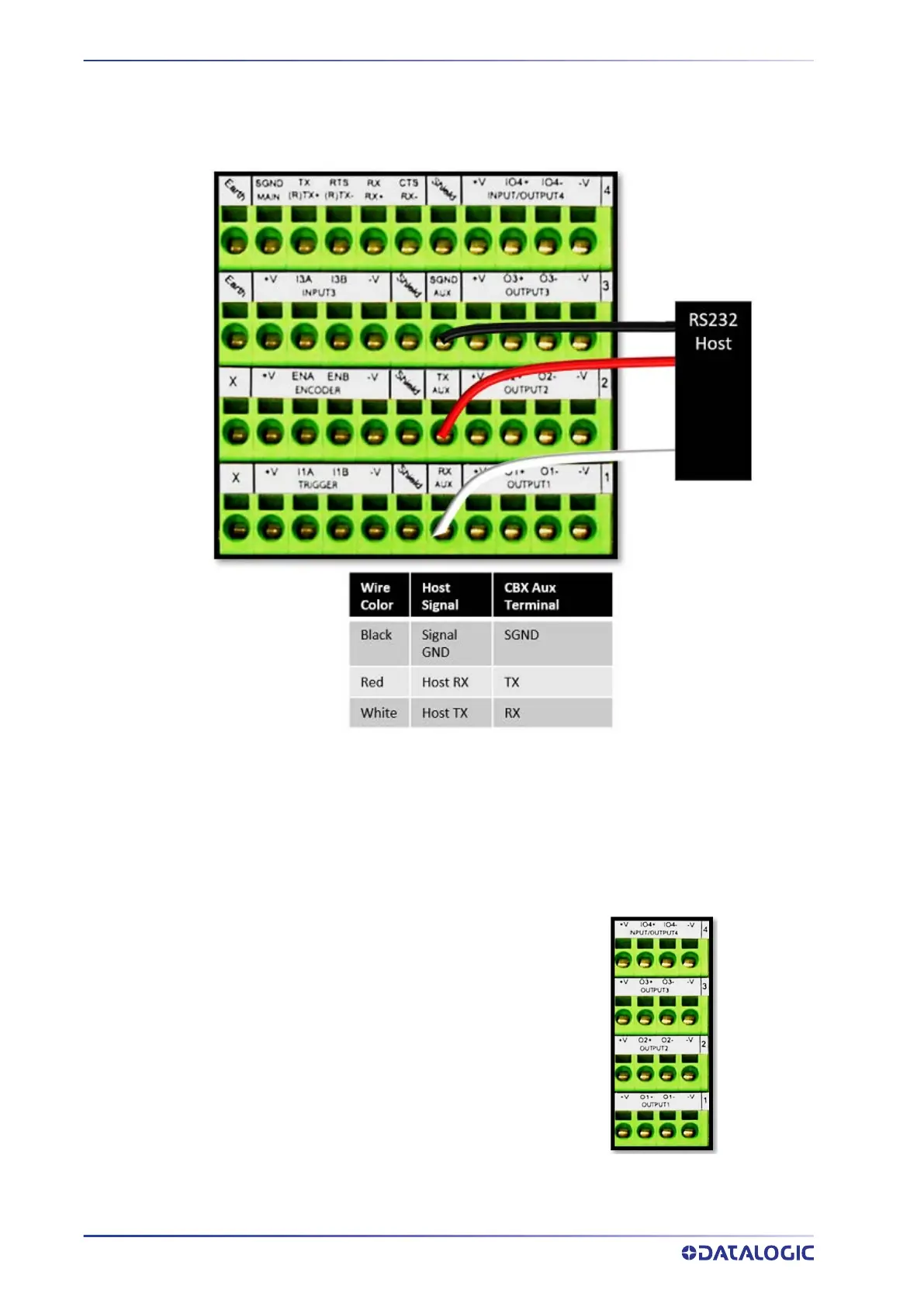
The 9-pin connector is normally used for quick/temporary connection. For a more per-
manent connection you can also use the CBX Box’s spring clam connectors, in particular
the positions labeled RX, AUX, TX and SGND AUX.
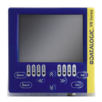
Digital Output Configuration from CBX510
The CBX510 includes an OUTPUTS block for wiring relays as needed for external acces-
sories. Output 4 is shared with Input 4, so it must be configured correctly using e-Genius
setup.
Schematics for Isolated and Non-Isolated digital outputs are provided below.
Outputs 1 - 4
Maximum Voltage 30V
Collector Current (pulse) 130 mA Max.
Collector Current (continuous) 40 mA Max.
Saturation Voltage (VCE) 1V at 10 mA Max.
Max. Power Dissipation 90 mW at 50 degrees C
ambient temperature.