CBX CONNECTION BOX INITIAL CONFIGURATION
PRODUCT REFERENCE GUIDE
36
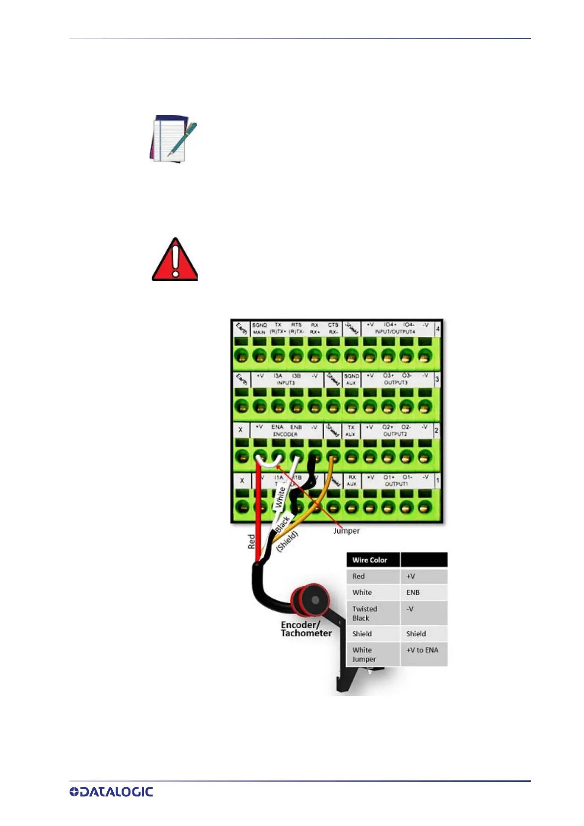
Encoder/Tachometer Wiring to CBX510
Barcode scanning applications often use a Tachometer/Encoder. The Tachometer/
Encoder is wired directly into the CBX510 terminal block. If your application uses a
tachometer follow the appropriate wiring diagram.
Encoder/Tachometer Wiring for NPN Output to CBX510
Inside the Tachometer is a switch that needs to be set to accommodate the settings of
your application. The switch allows you to set the type of wiring and the pulses per rev-
olution. For a typical system the pulses per revolution may be set to 192 or 240. In this
example we are wired for NPN communications. The switch settings are shown below.
NOTE: The Encoder/Tachometer signal can only be configured on CBX Port1
of the SC5100. Therefore the Encoder/Tachometer must be connected to
the CBX connected to the SC5100 Port 1.
WARNING: Some Photocraft tachometers may have a different color coding:
(+V) Red or White/Orange
(Signal) White or White/Blue
(Ground) Black or Orange/White