HOST INTERFACE
Data Device Corporation DS-BU-67301B-G
www.ddc-web.com
1/14
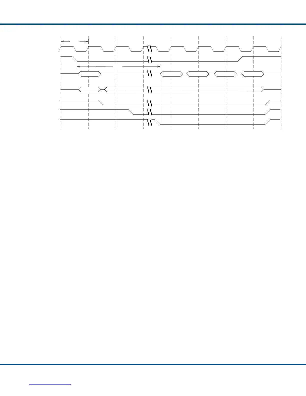
Figure 51. PCI Slave Burst Read - PCI Initiator Timing
Figure 52 through Figure 54 illustrate the operation of the Total-AceXtreme®’s PCI
Initiator interface. The Total-AceXtreme’s Initiator is activated by the host writing a
logic ‘1’ to the DMA Start bit of the DMA Command/Status Register. Figure 52 shows
tDMA_START, the delay from the end of the host write to the Total-AceXtreme’s
PCI Target interface (falling edge of TRDY#) to the falling edge of the Total-
AceXtreme’s REQ# output. By asserting REQ#, the Total-AceXtreme is vying to the
PCI arbiter to become the next bus master.
Once the arbiter responds by asserting the Total-AceXtreme’s GNT# input low, the
Total-AceXtreme’s PCI Initiator interface will begin its DMA burst write transfer, as
shown in Figure 53; or its DMA burst read transfer, as shown in Figure 54.
TRDY#
DEVSEL#
IRDY#
C/BE[3:0]#
FRAME#
tCLK
AD[31:0]
HOST_CLK
Data
Data
Data
Address
0x7
0x0
Data
tRead