HOST INTERFACE
Data Device Corporation DS-BU-67301B-G
www.ddc-web.com
1/14
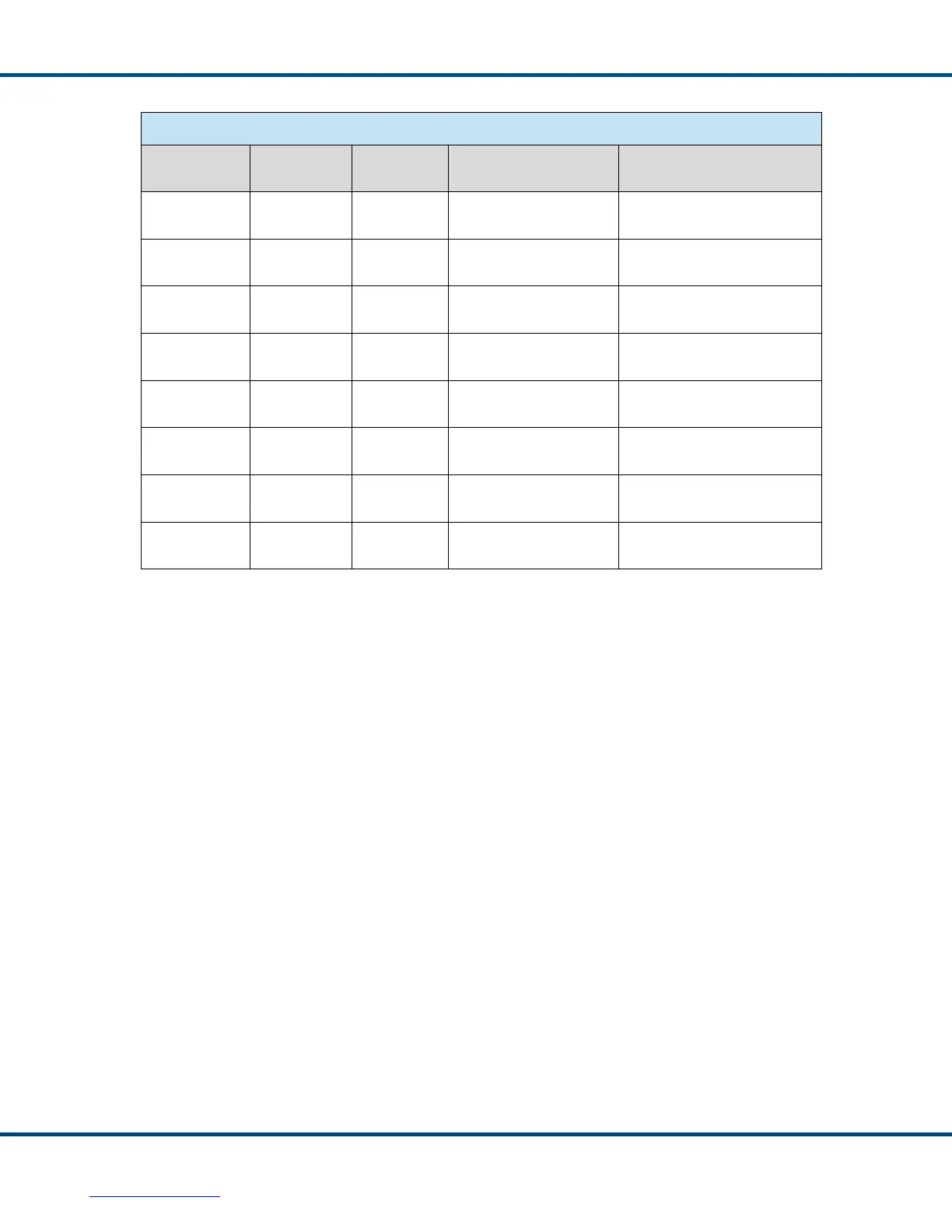
Table 5. Asynchronous 16-bit Mode Configuration Options
TRIG_SEL POL_SEL RD_nWR
FIRST WORD
TRANSFER
SECOND WORD
TRANSFER
1 1 1
MSW_nLSW = 0
CPU RAM 31:16
MSW_nLSW = 1
CPU RAM 15:0
1 1 0
MSW_nLSW = 0
CPU RAM 31:16
MSW_nLSW = 1
CPU RAM 15:0
1 0 1
MSW_nLSW = 1
CPU RAM 31:16
MSW_nLSW = 0
CPU RAM 15:0
1 0 0
MSW_nLSW = 1
CPU RAM 31:16
MSW_nLSW = 0
CPU RAM 15:0
0 1 1
MSW_nLSW = 1
CPU RAM 15:0
MSW_nLSW = 0
CPU Buffer 31:16
0 1 0
MSW_nLSW = 1
CPU RAM 15:0
MSW_nLSW = 0
CPU RAM 31:16
0 0 1
MSW_nLSW = 0
CPU RAM 15:0
MSW_nLSW = 1
CPU RAM 31:16
0 0 0
MSW_nLSW = 0
CPU RAM 15:0
MSW_nLSW = 1
CPU RAM 31:16
6.3.1.2 Asynchronous Mode Connection Diagrams
Figure 7 through Figure 10 show the four possible Asynchronous mode interface
configurations, including the four combinations of 32-bit, 16-bit, non-multiplexed, and
multiplexed.