OVERVIEW
Data Device Corporation 8 DS-BU-67301B-G
www.ddc-web.com
1/14
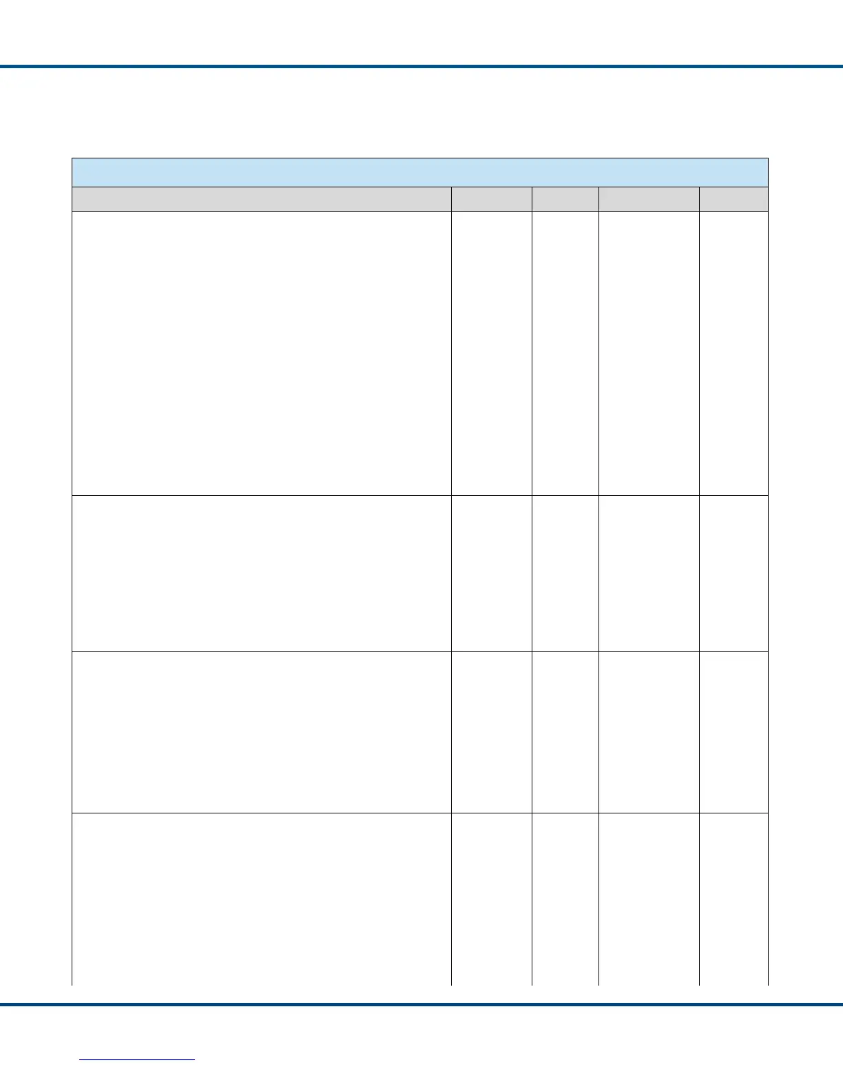
2.2 Specifications
Table 1. Total-AceXtreme® Series Specifications
PARAMETER MIN TYP MAX UNITS
ABSOLUTE MAXIMUM RATINGS
Supply Voltage (Note 11)
Logic +3.3V (V
DDIO
) -0.3 — 4.0 V
Core +1.8V -0.3 — 2.0 V
PLL +1.8V -0.3 — 2.0 V
• Transceivers +3.3V (during transmit)
• DC Input or Output Logic Voltage
-0.3
-0.3
—
—
4.5
V
DDIO
+0.3, or
4.0 (which ever
is less)
V
V
Logic
3.3V Logic Input or Output Range -0.3 — V
DDIO
+0.3, or
4.0 (which ever
is less)
V
RECEIVER
Differential Input Impedance (Notes 1 – 6)
• +3.3V Transformer Coupled 1.0 KΩ
Input Voltage Range
Threshold Voltage (Transformer Coupled)
0.86
0.200
—
14.0
0.860
V
PK-PK
V
PK-PK
Common Mode Voltage ±10 V
peak
TRANSMITTER
Differential Output Voltage
Transformer Coupled Across 70
Ω
, Measured on Bus (Note 9)
20 21.5 27 V
PK-PK
Output Noise, Differential 14 mV
RMS
Output Offset Voltage, Transformer Coupled Across 70 Ω
-250 250 mV
PK
Rise/Fall Time 100 150 300 ns
LOGIC
VIH
All logic inputs, including HOST_CLK/PCI_CLK and CLK_IN 2.0 V
DDIO
+ 0.3 V
VIL
All logic inputs, including HOST_CLK/PCI_CLK and CLK_IN -0.3 0.8 V
Schmidt Hysteresis
HOST_CLK/PCI_CLK and CLK_IN 0.4 0.7 V
 Loading...