BUILT- IN TEST
Data Device Corporation DS-BU-67301B-G
www.ddc-web.com
1/14
ordering of the signals in the scan chain is defined in the BSDL file that is included in
the Total-AceXtreme® Development Kit.
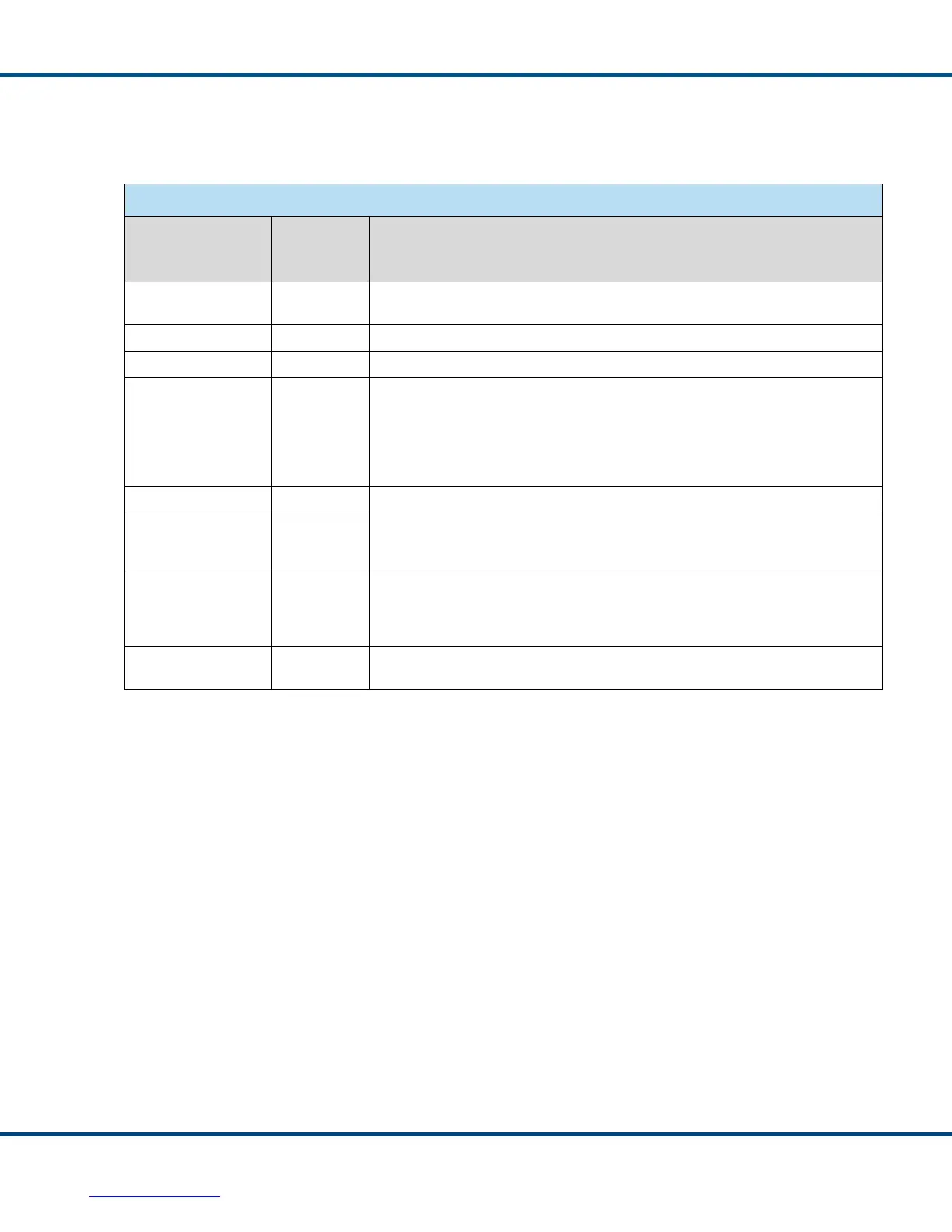
Table 2. Supported JTAG Functions
JTAG Instruction Instruction
Register
Value
Description
BYPASS 0b111 The BYPASS Instruction is used to allow data to connect directly from
JTAG_TDI pin to the JTAG_TDO pin.
Reserved 0b110 Reserved
Reserved 0b101 Reserved
USERCODE 0b100 The USERCODE specifies which version of the Total-AceXtreme is present.
0x000000FF denotes the BU-67301B0T0L-E02
Other values are reserved.
IDCODE 0b011 The IDCODE for the Total-AceXtreme is 0x0590003F
HIGHZ 0b010 Sets all the Outputs and Bidirectional Outputs to a high impedance state. The
HIGHZ can be used to determine excessive leakage current during the Total-
AceXtreme’s manufacturing phase.
SAMPLE/PRELOAD 0b001 The SAMPLE function provides the ability to capture the current state of the I/O
pins. The Preload allows for JTAG to preload the JTAG cells with values which
will not actually be loaded until the appropriate instruction (such as EXTEST) is
entered.
EXTEST 0b000 The EXTEST Instruction allows for a test vector to be applied from the
Boundary Scan Register to the external pins of the Total-AceXtreme.
Please contact DDC for further information on using the Boundary Scan feature.