HOST INTERFACE
Data Device Corporation DS-BU-67301B-G
www.ddc-web.com
1/14
nDATA_RDY
CPU_nSTOP
HOST_CLK
CPU_DATA
CPU_WORD_EN[1:0]
RD_nWR
MEM_nREG
CPU
_ADDR
nDATA_STRB
nSELECT
CPU_nLAST
MSW_nLSW
tRDD
tLS
tCLK
tDH
tRDD
tAS
tAS
tAS
tCS
tDH
Address
tCH
tAS
tAH
tAH
Data
Data
Data
Data
Data
Data
Data
Data
Data
tAH
Data
tDS
tWait
tLH
tLS
tLH
tAH
tSS
tSH
tAS
tAH
tAH
tSHC
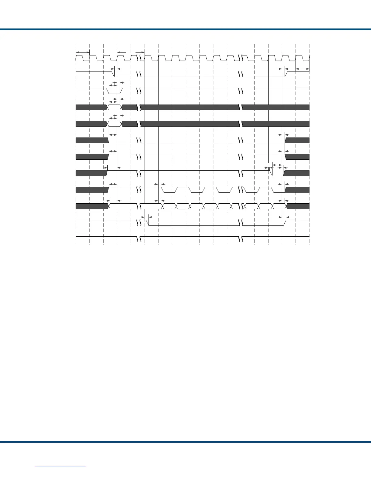
Figure 41. Synchronous, Non-Multiplexed Address - 16-bit Sequential Burst Write
Transfer Timing
Figure 41 Notes:
1. A one-clock-cycle wide pulse of nDATA_STRB (low) when nSELECT is
asserted (low) and valid address presented initiates the sequential burst write
transfer. nSELECT must be asserted low through the full burst cycle. The
nDATA_RDY output is initially asserted low on the clock cycle prior to the
cycle in which the Total-AceXtreme® reads the first 16-bit data word from the
data bus. CPU_nLAST must be asserted high until the last 16-bit word is to be
written. On the rising clock edge following CPU_nLAST asserting low, the
Total-AceXtreme reads the last 16-bit word from the data bus, and
nDATA_RDY is de-asserted (high). At this time (or later) nSELECT must be
de-asserted high, completing the burst write transfer.
2. For 16-bit accesses, CPU_WORD_EN[1:0] must be ‘11’ through the full
transfer cycle.
3. Unless the Total-AceXtreme command FIFO is full, CPU_nSTOP is not
asserted, and will remain high.