Chapter 2 Installation and Wiring|VFD-M-D Series
2-6 Revision Jan. 2007, MDE2, SW V1.05
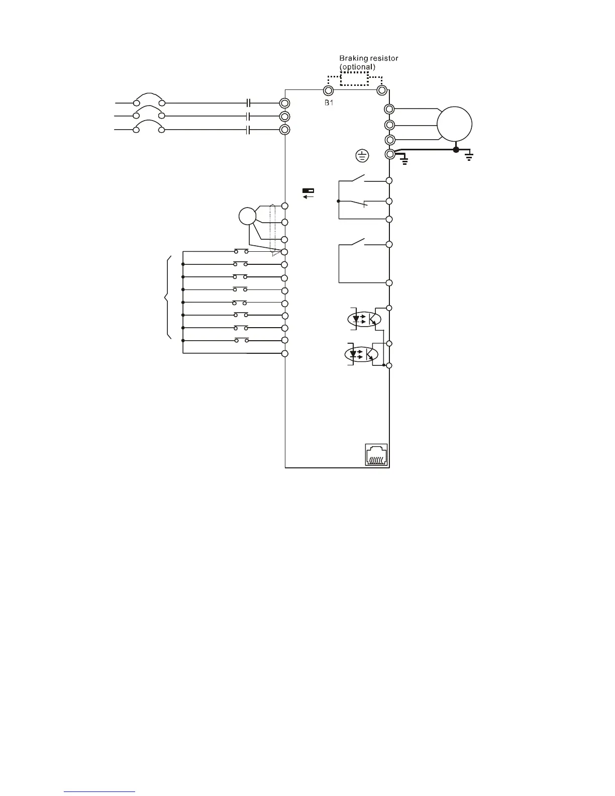
B2
VP
A
B
GND
MI1
MI2
MI3
MI4
FWD
REV
MI5
DCM
FWD/STOP
REV/STOP
Digital Signal Common
* Don't apply the mains voltage directly
to above terminals.
R(L1)
S(L2)
T(L3)
Fuse/NFB(None Fuse Breaker)
R(L1)
S(L2)
T(L3)
U(T1)
V(T2)
W(T3)
IM
3~
RS-485
Motor
Serial interface
1:
2:
5:NONE
6: Reserved
Reserved
Reserved
3: SG-
4: SG+
E
RA1
RB1
RC1
Multi-function contact output
240VAC 2.5A
120VAC 5A
24VDC 5A
output of multi-function contact
(open collector)
48VDC50mA
Common o terminal of
photocoupler
utput
RA2
RC2
Multi-function contact output
240VAC 2.5A
120VAC 5A
24VDC 5A
PG
A
B
+12/24V
DCM
24V
12V
VP Voltage
Factory
setting
Emergency stop
Force stop
Demo mode
Door open limit signal
Door close limit signal
Mo1
Mo2
MCM
61
←
 Loading...


