Chapter 5 Parameters|VFD-M-D Series
5-62 Revision Jan. 2007, MDE2, SW V1.05
Group 6: Digital Output Parameters
6 - 00 Multi-function Output Relay (RA1, RB1, RC1)
Factory Setting: 00
6 - 01 Multi-function Output Relay (RA2, RC2)
Factory Setting: 00
6 - 02
Multi-function Output Terminal MO1
Factory Setting: 00
6 - 03 Multi-function Output Terminal MO2
Factory Setting: 00
6 - 04 Multi-function Output Terminal MO3 (communication)
Factory Setting: 00
6 - 05 Multi-function Output Terminal MO4 (communication)
Factory Setting: 00
6 - 06 Multi-function Output Terminal MO5 (communication)
Factory Setting: 00
6 - 07 Multi-function Output Terminal MO6 (communication)
Factory Setting: 00
Settings 00 to 26
These parameters can be used for the external terminal output.
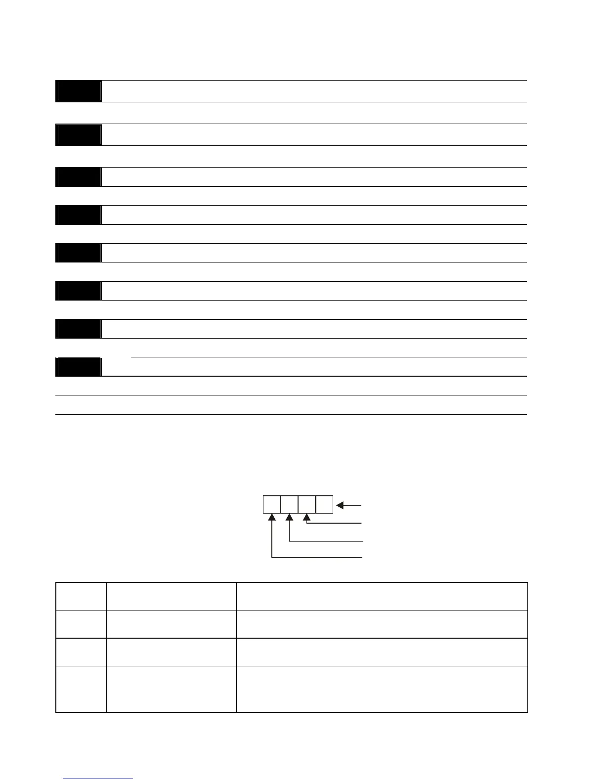
It needs to set MO3 to MO6 to ON/OFF by communication and the corresponding address for
MO3 to MO6 is 2209H as shown in the following.
123 0
0=OFF
1=ON
MO3
MO4
MO5
MO6
Weights Bit
2
3
2
2
2
1
2
0
Settings Function Description
00 No Function
01 AC Drive Operational
Active when there is an output from the drive or RUN
command is “ON”.
02
Master Frequency
Attained
Active when the AC motor drive reaches the output
frequency setting.
 Loading...


