Chapter 2 Installation and Wiring|VFD-M-D Series
2-10 Revision Jan. 2007, MDE2, SW V1.05
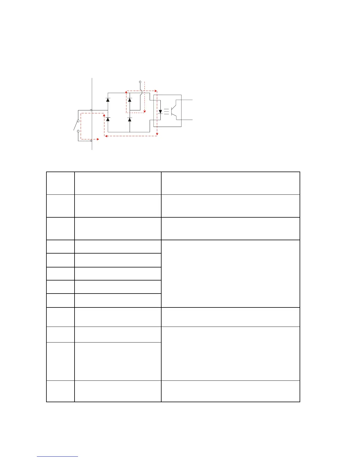
2.4.4 Control Terminals
Circuit diagram for digital inputs (NPN mode)
+24
NPN Mode
multi-input
terminal
Internal CircuitDCM
Terminal symbols and functions
Terminal
Symbol
Terminal Function
Factory Settings
ON: Connect to DCM
FWD Forward-Stop command
ON: Run in FWD direction (door close)
OFF: Stop acc. to Stop Method
REV Reverse-Stop command
ON: Run in REV direction (door open)
OFF: Stop acc. to Stop Method
MI1 Multi-function Input 1
MI2 Multi-function Input 2
MI3 Multi-function Input 3
MI4 Multi-function Input 4
MI5 Multi-function Input 5
Refer to Pr.5-00 to Pr.5-04 for programming the
Multi-function Inputs.
DCM Digital Signal Common Common for digital inputs.
A A-phase Input Terminal
B B-phase Input Terminal
This terminal is used for feedback pulse input. It
also can be used as multi-function input
terminal.
Maximum pulse: 500KP/Sec
Support types: voltage output and open
collector.
VP +12/24 Vdc Output
It can apply +12 or +24 VDC power for encoder
and change by switch (12V/100mA, 24V/50mA).
 Loading...


