Chapter 5 Parameters|VFD-M-D Series
5-16 Revision Jan. 2007, MDE2, SW V1.05
0 - 03
Start-up Display Selection
Factory Setting: 00
Settings 00 Display the frequency command value. (F)
01 Display the actual output frequency (H)
02 Display the content of user-defined unit (U)
03 Multifunction display, see Pr.0-04
04 FWD/REV command
This parameter determines the start-up display page after power is applied to the drive.
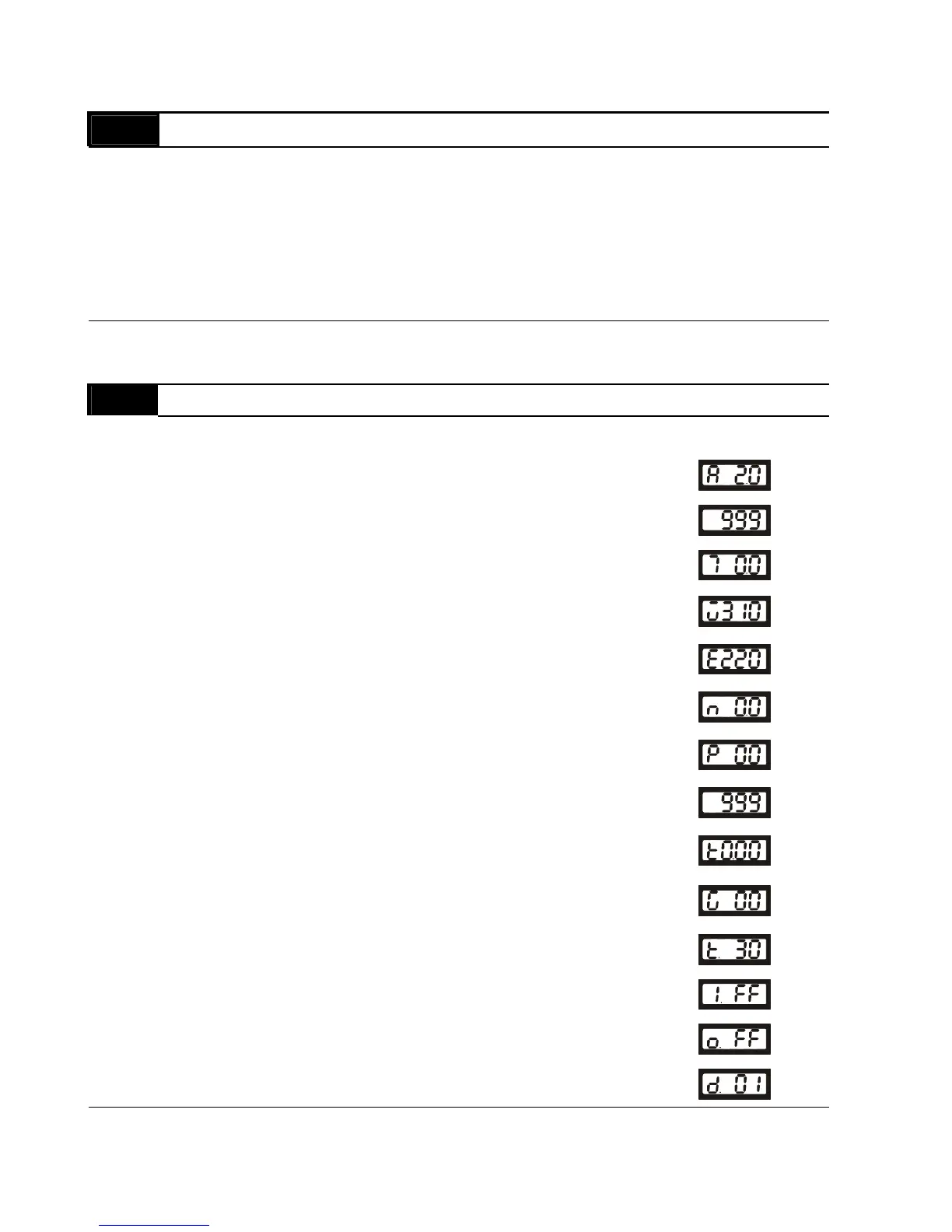
0 - 04 Content of Multi-Function Display
Factory Setting: 00
Settings 00 Display the output current in A supplied to the motor
01
Display the pulses
02 Display the walking distance and step speed (x.yy.y)
03
Display the actual DC BUS voltage in VDC of the AC
motor drive
04
Display the output voltage in VAC of terminals U, V, W
to the motor.
05
Display the power factor angle in º of terminals U, V, W
to the motor.
06
Display the output power in kW of terminals U, V and W
to the motor.
07
Display the actual motor speed in rpm (enabled in
vector control mode or PG (Encoder) feedback control)
08
Display the estimated value of torque in Nm as it relates
to current.
09
Display PG encoder feedback pulses/10ms.
Display value= (rpm*PPR)/6000 (see note)
10
Display the temperature of heat sink in °C.
11 Display external input terminal status (I.)
12 Display external output terminal status (o.)
13 Display communication address (d.)
This parameter sets the display when Pr. 0-03 is set to 03.
 Loading...


