Chapter 5 Parameters|VFD-M-D Series
Revision Jan. 2007, MDE2, SW V1.05 5-35
2 - 13 Electrical Gear A Unit: 1
Settings 01 to 5000 Factory Setting: 100
2 - 14 Electrical Gear B Unit: 1
Settings 01 to 5000 Factory Setting: 100
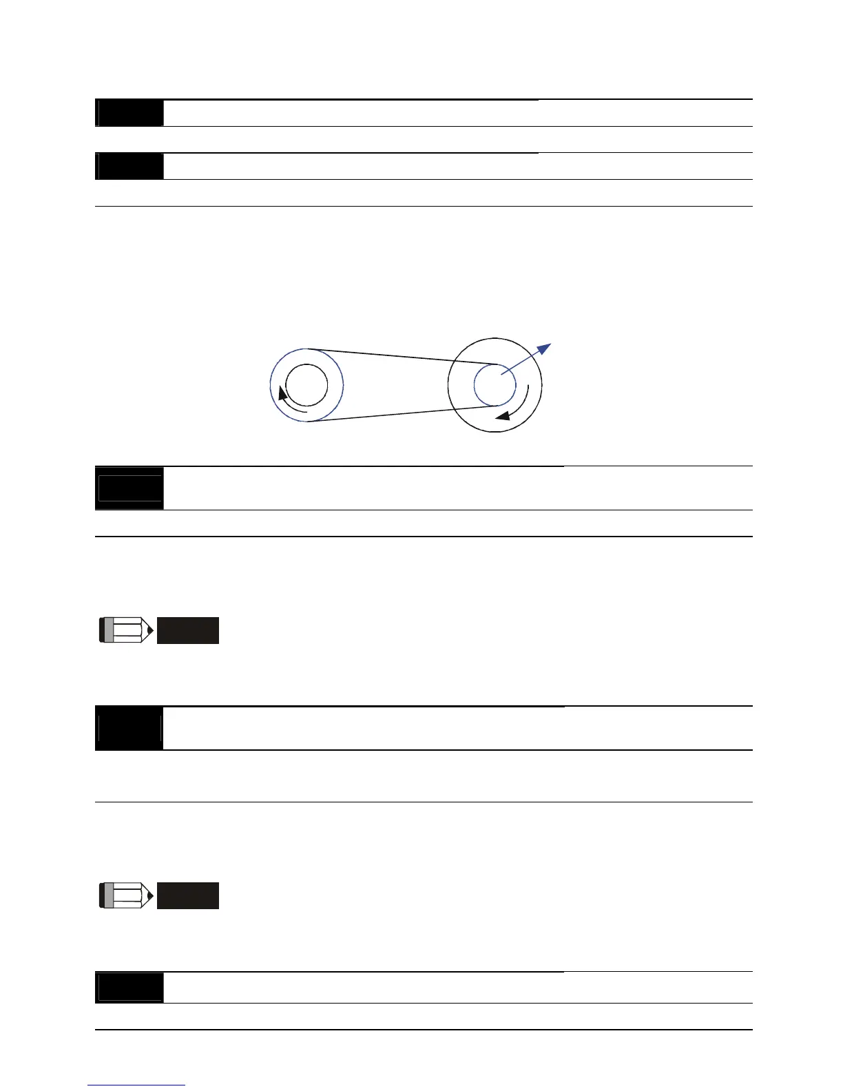
A Pulse Generator (PG) or encoder is not at motor side, it can use these parameters (Pr.2-13
and Pr.2-14) to set the deceleration ratio of motor and encoder (electrical gear A/electrical
gear B). The actual output frequency will be based on the following equation:
Output frequency = PG frequency x electrical gear A (Pr.2-13) / electrical gear B (Pr.2-14).
PG
Motor
Electrical Gear B(2-14)Electrical Gear A(2-13)
2 - 15
ASR (Auto Speed Regulation for door open) control (with
PG only) (P)
Unit: 0.1
Settings 0.0 to 10.0 Factory Setting: 0.5
This parameter specifies Proportional control and associated gain (P), and is used for speed
control with PG (encoder) feedback.
NOTE
The parameter can be set during operation for easy tuning.
2 - 16
ASR (Auto Speed Regulation for door open) control (with
PG only) (I)
Unit: 0.01
Settings 0.00 to 100.00 Factory Setting: 1.00
0.00 disable
This parameter specifies Integral control and associated gain (I), and is used for speed control
with PG (encoder) feedback.
NOTE
The parameter can be set during operation for easy tuning.
2 - 17 PG Slip Compensation Limit Unit: 0.01
Settings 0.00 to 10.00 Hz Factory Setting: 10.00
 Loading...


