6-4
95-8533
18.2
IECEx: IECEx ULD 10.0004X.
Ex nA nC IIC T4 GC.
Tamb = –40°C to +85°C.
Note:
Refer to Appendix C for ATEX and IECEx
approval details and Special Conditions for
Safe Use.
Refer to Appendix D for USCG Approval details.
INPUT / INITIATING DEVICE CIRCUITS
UNSUPERVISED INPUT—
Two state input (on/off).
Normally open contact.
SUPERVISED INPUT (OPEN CIRCUIT)—
For Class A and Class B wiring.
Two state input (active/trouble):
– End of Line Resistor 10 K ohms nominal
– Open Circuit > 45 K ohms
– Active Circuit < 5 K ohms.
SUPERVISED INPUT
(OPEN AND SHORT CIRCUIT)—
For Class A and Class B wiring.
Three State input (active/short/open):
– End of Line Resistor 10 K ohms nominal
– In Line Resistor 3.3 K ohms nominal
– Open Circuit > 45 K ohms
– Short Circuit < 250 ohms
– Active Circuit 2.5 K ohms to 5 K ohms.
INPUT, TYPES—
Configurable for static logic applications:
– Fire Alarm
– Supervisory
– Trouble
– High Gas Alarm
– Low Gas Alarm
– Other.
For Class A wiring on inputs, configure adjacent
channels for Class A wiring and connect both
channels to single contact device(s).
INPUT CIRCUITS – TWO WIRE SMOKE/HEAT
TYPE—
Supervised Input, Class B:
Up to 15 two wire detectors per circuit.
Maximum line resistance 50 ohms.
5K ohm EOL.
Open circuit fault impedance 22k ohms.
OUTPUT / NOTIFICATION / RELEASING
OR UNSUPERVISED DEVICE CIRCUITS
UNSUPERVISED OUTPUT RATING
(Per Channel)—
2 amperes at 30 Vdc maximum.
Automatic short circuit protection provided.
Instantaneous short circuit current < 15
amperes.
Note: Voltage available at outputs is dependent
on input voltage (V
out
≈ V
in
– 0.5 Vdc).
OUTPUT STYLE—
Form "A" normally off.
RESPONSE TIME—
Output actuates in <0.15 second after
acknowledging an alarm command
message.
A B C A B C A B C A B C
A B C A B C A B C A B C
1
6
1 6
1 2 3
4 5
6
7
8
A B C A B C A B C A B C
A B C A B C A B C A B C
1
6
1 6
1 2 3
4 5
6
7
8
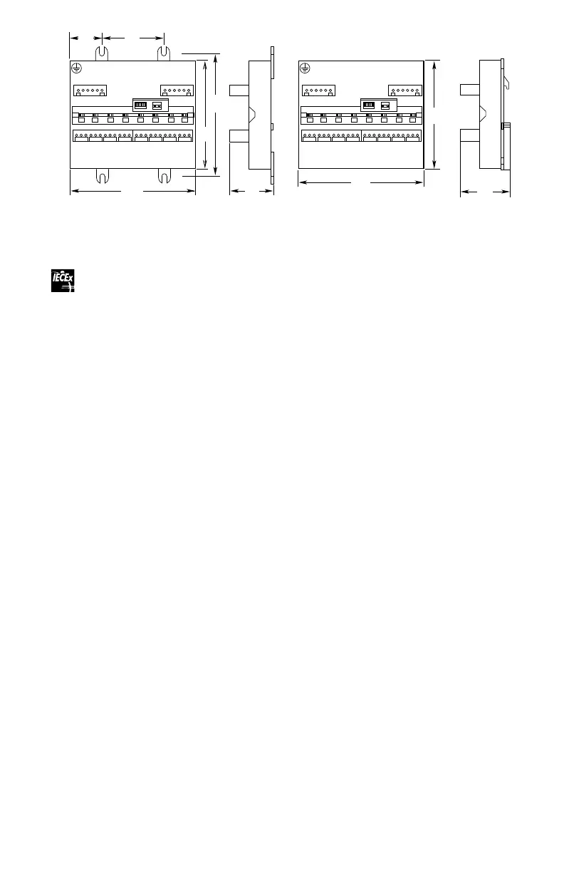
4.5
(11.3)
5.02
(12.7)
2.5
(6.4)
1.35
(3.4)
5.2
(13.2)
1.66
(4.2)
5.2
(13.2)
1.9
(4.8)
4.5
(11.3)
A2449
PANEL MOUNTING DIMENSIONS DIN RAIL MOUNTING DIMENSIONS
Figure 6-3—Dimensions of the EDIO / DCIO / Relay Module / AIM in Inches (Centimeters)