3-12
95-8533
18.2
When controller and power supplies are
installed in separate NRTL cabinets, two
power cables from two distribution circuits are
required, so that if one is lost, the controller
will continue to operate and signal a trouble
condition. The power circuit must be protected
against physical damage.
Shields on power cables must be connected to
chassis ground (earth).
Connector P2, Terminals 5 to12 —
Unsupervised Digital Input Channels 1 to 4
Connector P3, Terminals 13 to 20 —
Unsupervised Digital Input Channels 5 to 8
See Figure 3-4 for example. Only channel 1 is
shown in Figure 3-4. The information is typical
for channels 2-8.
Connector P4, Terminals 21 to 32 —
Unsupervised Relay Output Channels 1 to 4
Connector P5, Terminals 33 to 44 —
Unsupervised Relay Output Channels 5 to 8
See Figure 3-5 for example. Only channel 1 is
shown in Figure 3-5. The information is typical
for channels 2-8.
NOTE
Channel software configurations
include all panel indicator functions to
automatically mimic the controller front
panel indicators.
Connector P6, Terminals 45, 46 & 47 —
Trouble Relay
The Trouble relay is not configurable. In the
normal condition, the relay coil is energized,
closing the N.O. contact (terminals 45-46) and
opening the N.C. contact (terminals 45-47).
The relay coil is de-energized in the trouble
condition.
Connector P7, Terminals 48 to 53 —
LON Signaling Line Circuit Terminals
The LON loop is wired so that the controller’s
LON COM 1 is connected to the field device’s
COM 2 connection. The field device’s COM 1 is
wired to the next device’s COM 2 connection.
This continues through the last field device
on the loop. The last field device’s COM 1
is then wired back to the Controller’s COM 2
connection. LON A and B polarities must be
maintained throughout the loop (i.e., always
wire A to A and B to B between the devices).
Port Pinout (6-position connection terminal
block)
48 — COM 1 shield connection
49 — "B" side of signaling circuit for COM 1
50 — "A" side of signaling circuit for COM 1
51 — COM 2 shield connection
52 — "B" side of signaling circuit for COM 2
53 — "A" side of signaling circuit for COM 2
NOTE
Refer to Figures 3-12A and 3-12B for
location of termination jumpers.
Jumper P24 – RS-485 Termination Jumper
1-2 Unterminated
2-3 Terminated 121 ohms (factory setting)
Transceiver input impedance: 68 kohm
Jumper P25 – LON COM 1 Termination
1-2 COM 1 Terminated (factory setting)
2-3 COM 1 Unterminated (Redundancy)
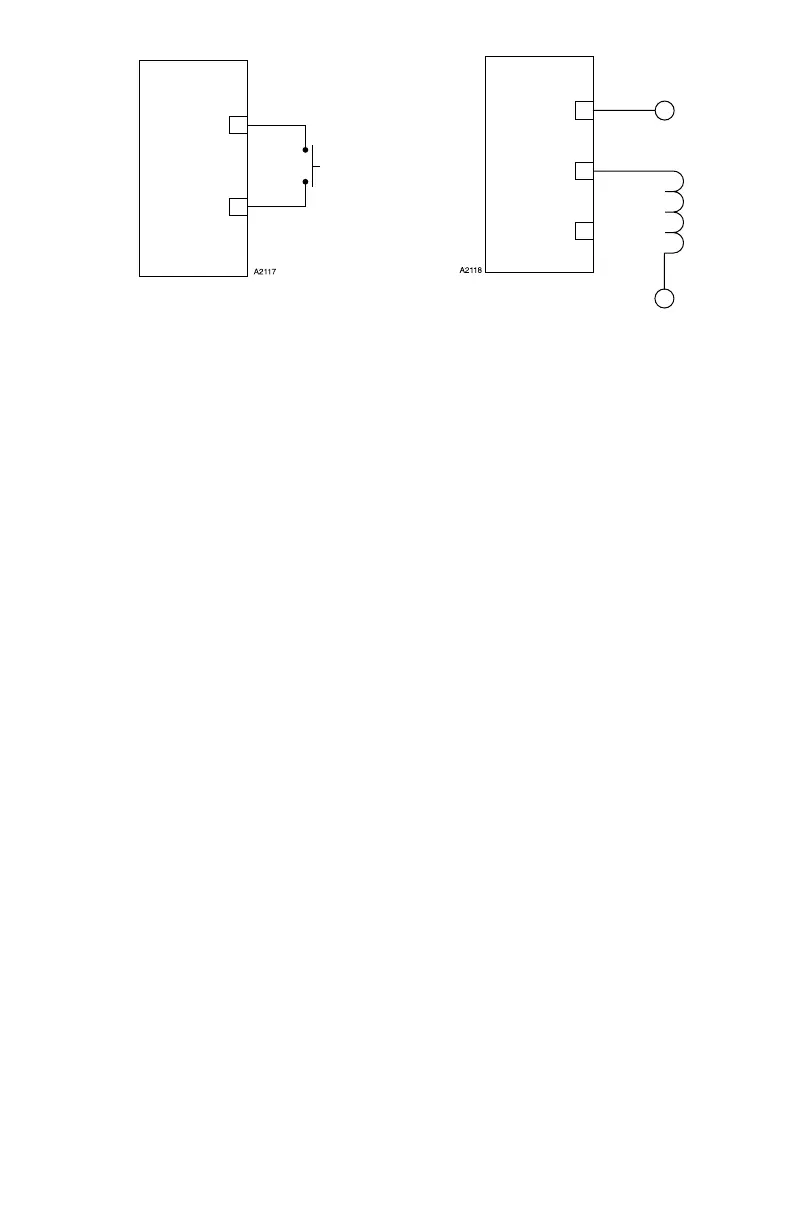
Figure 3-4—Unsupervised Input Wiring
COMMON, –
INPUT, +
P2
6
5
Figure 3-5—Unsupervised Relay Output
N. C.
23
N. O.
22
COMMON
21
+
–