3-18
95-8533
18.2
The media converter can be connected to either
of the EQP controller RS-485 communication
ports (Port 1 or Port 2). Figure 3-14 illustrates
a typical Class B wiring connection (single
mode) between two EQP controllers in a
redundant configuration using Port 1. Note: If
Port 2 is preferred, the Serial Interface Board
must be purchased.
Figure 3-13 shows a typical Class X wiring
connection (single mode).
Figure 3-14 shows a typical Class X wiring
connection for Phoenix (multi mode).
For more information regarding selection and
installation of fiber optic media, please contact
Det-Tronics customer service.
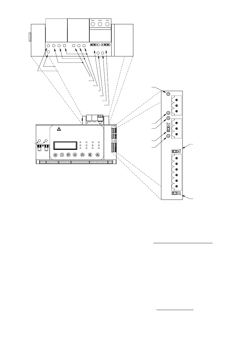
Figure 3-10B—Location of Termination Jumpers, Communication Indicator LEDs, and Communication Ports
for Controller with Ethernet Interface Board
1
P25
3
1
P26
3
P24
1
3
RS-232 Receive LED (Green)
Ethernet Receive LED (Green)
RS-232 Receive LED (Green)
Ethernet Port Ready LED (Blue)
RS-485 Transmit LED (Amber)
RS-485 Transmit LED (Amber)
RS-485 Termination Jumper
P6: RS-485 Termination Jumper
P5: RS-485 Ground Fault
Monitor Jumper
A B
Channel
Indicators
RS-485 Receive LED (Green)
RS-485 Receive LED (Green)
RS-232 Transmit LED
(Amber)
Ethernet Transmit LED (Amber)
RS-232 Transmit LED (Amber)
LON COM 2
Termination Jumper
LON COM 1
P6
1 3
P5
1 3
RJ45
PORT 4
RJ45
PORT 3
P10
PORT 2
P
O
R
T
1
EAGLE QUANTUM PREMIER
Safety System Controller
Fire Alarm
Inhibit
Power
SuprHigh Gas
Trouble
Cntrl Flt
Lon FaultLow Gas Ack Silence
Out Inhibit
Eagle Quantum Premier
Time & Date
Cancel Enter Next Previous Reset Acknowledge Silence
DET-TRONICS
®
The maximum distance of a particular optic
link given the optical budget is calculated as:
Fiber Length = [Optical budget] – [Link Loss]
[Fiber Loss / km]
where link loss includes number of end
connectors, splices and safety margin.
Example: 10 db link budget
Cable Attenuation: 0.4 db / km
2 connectors: (1 each end) with
0.5 db ea.
Safety margin: 3.0 db max
Max. Distance = 10 – (2 x 0.5) – 3.0 = 15 km
0.4