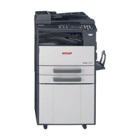
ineo 161
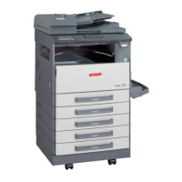
ineo 210
GeneralMaintenanceAdjustment / Setting
Troubleshooting
Field Service Ver. 1.0 Apr. 2005
iv
10.3.3 COUNTER.................................................................................................. 97
10.3.4 DISPLAY................................................................................................... 101
10.3.5 FUNCTION ............................................................................................... 102
10.3.6 ADMIN. REGISTRATION.......................................................................... 105
10.3.7 FIXED ZOOM CHANGE........................................................................... 105
10.3.8 FACTORY TEST ....................................................................................... 106
10.3.9 CLEAR DATA ............................................................................................ 107
11. Security............................................................................................................... 109
11.1 Security Function Setting Procedure................................................................ 109
11.1.1 Procedure ................................................................................................. 109
12. Mechanical adjustment ....................................................................................... 110
12.1 Adjustment of the Position of the Scanner and 2nd/3rd Mirrors Carriage ........ 110
12.2 CCD Unit Position Adjustment.......................................................................... 111
12.3 Adjustment of the Gap between the Doctor Blade and Sleeve Roller (Db Adjust-
ment)112
12.4 Manual Bypass (for the optional AD-504) CD Registration Adjustment *ineo 210
only114
Troubleshooting
13. Introduction ......................................................................................................... 115
13.1 Electrical Components Check Procedure......................................................... 115
13.1.1 Sensor ...................................................................................................... 115
13.1.2 Switch ....................................................................................................... 116
13.1.3 Solenoid.................................................................................................... 116
13.1.4 Clutch........................................................................................................ 116
13.1.5 Motor......................................................................................................... 117
14. Jam Display......................................................................................................... 118
14.1 Misfeed Display ................................................................................................ 118
14.1.1 Display Resetting Procedure .................................................................... 118
14.2 Sensor layout.................................................................................................... 119
14.2.1 System Mounted with DF-502, PF-502 and MB-501................................ 119
14.3 Solution ............................................................................................................ 120
14.3.1 Initial Check Items .................................................................................... 120
14.3.2 Misfeed at the Paper Feed Tray/1 Paper Take-up Section........................ 121
14.3.3 Misfeed at the Manual Bypass Paper Take-up Section............................. 122
14.3.4 Misfeed at the Multiple Bypass Paper Take-up Section
(When the optional Multiple Bypass MB-501 is mounted)123
14.3.5 Misfeed at the Paper Feed Unit Paper Take-up/Vertical Transport Section
(When the optional Paper Feed Unit PF-502 is mounted)124