Field Service Ver. 1.0 Apr. 2005 6. Other
31
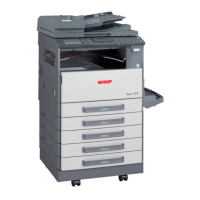
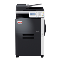
ineo 161
ineo 210
Maintenance
6.3 Disassembly/Assembly procedure
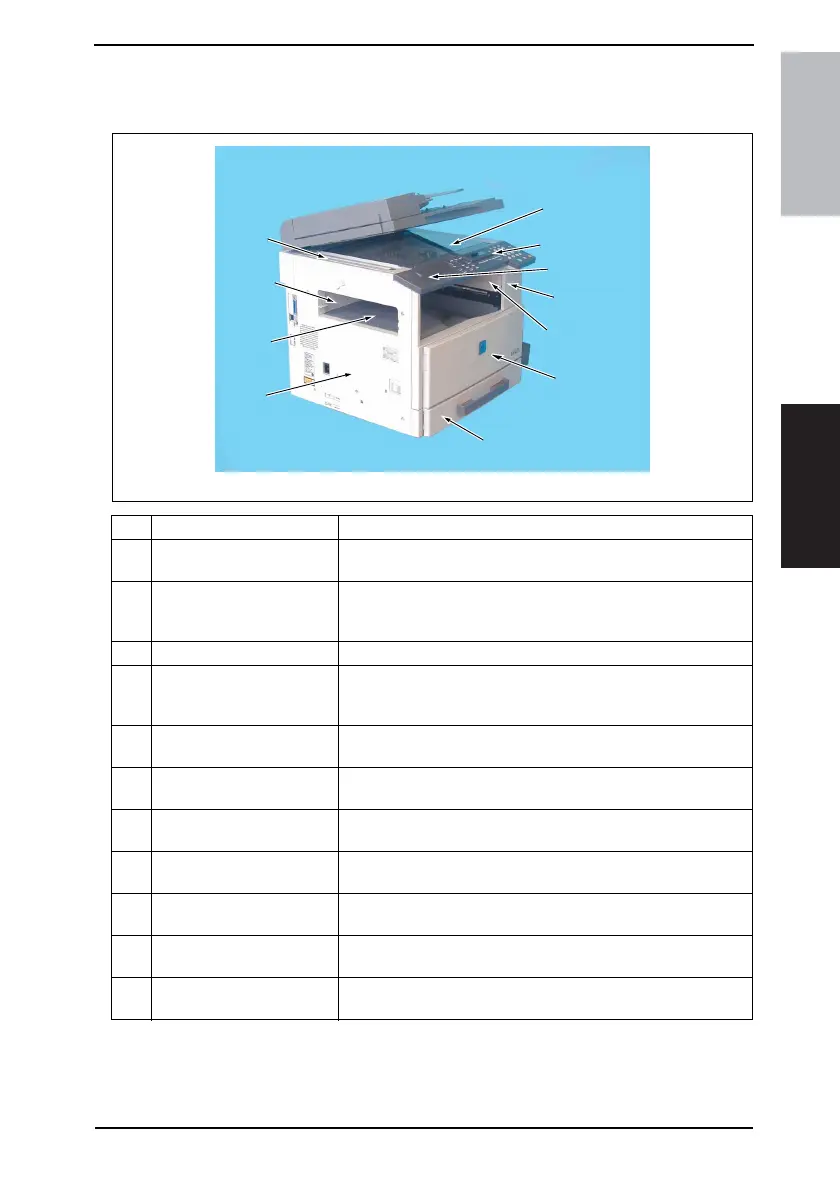
6.3.1 Exterior Parts
No. Part Name Removal Procedure
1 Original Glass
Remove the Original Scanning Glass. → Remove one screw. →
Remove the holding bracket. → Remove the Original Glass.
2 Control Panel
Remove the Control Panel Left Cover. → Remove two screws. →
Remove one flat cable and unplug one connector. → Remove the
Control Panel.
3 Control Panel Left Cover Remove one screw. → Remove the Control Panel Left Cover.
4 Front Cover
Remove the Control Panel. → Slide out the Paper Feed Tray/1. →
Open the Front Door. → Remove six screws. → Remove the Front
Cover.
5 Paper Exit Cover
Remove the Front Cover. → Remove one screw. → Remove the
Paper Exit Cover.
6 Front Door
Open the Front Door. → Snap off one C-clip. → Slide the Front
Door to the right and pull it off.
7 Tray 1
Slide out Tray/1. → Remove two screws. → Remove the fixing
brackets on the right and left ends of Tray/1. → Remove Tray/1.
8Left Cover
Remove the Front Cover. → Remove five screws. → Remove the
Left Cover.
9 Paper Exit Tray
Remove the Front Cover. → Remove two screws. → Remove the
Paper Exit Tray.
10 Rear Inside Cover
Remove the Left Cover. → Remove the Paper Exit Tray. →
Remove two screws. → Remove the Rear Inside Cover.
11 Original Scanning Glass
Remove the Left Cover. → Remove two screws. → Remove the
Original Scanning Glass.
4035D047AB
1
10
9
6
2
8
4
5
7
3
11