Field Service Ver. 1.0 Apr. 2005 15. Malfunction code
145
ineo 161
ineo 210
Troubleshooting
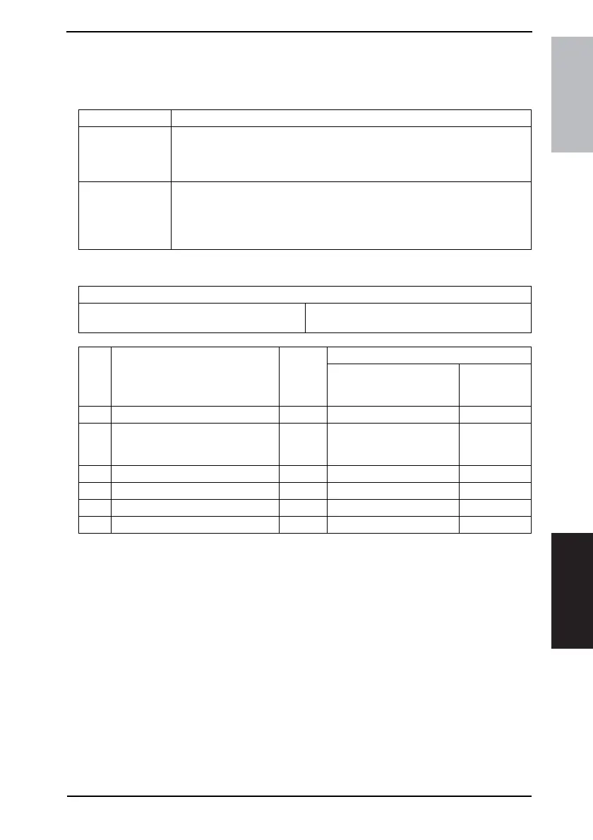
15.3.14 C0F32: Faulty ATDC Sensor
15.3.15 C0F33: Improperly Adjusted ATDC Sensor
A. Detection Timing
B. Action
Trouble Code Description
C0F32
• The measurement taken by the ATDC Sensor (UN1) at a time 2.0 sec. after the
Main Motor (M1) has started turning is less than 5% (greater than 4.63 V).
• The measurement taken by the ATDC Sensor (UN1) at a time 2.0 sec. after the
Main Motor (M1) has started turning is 19% or more (1.41 V or less).
C0F33
• The adjustment of the ATDC control voltage is not completed within 1 sec. after
sampling has started of the ATDC Sensor (UN1) as part of an operation of
ATDC Sensor Automatic Adjustment.
• The ATDC Sensor control voltage falls outside the range of 5.39 V to 8.15 V
during an operation of ATDC Sensor Automatic Adjustment.
Relevant Electrical Components
ATDC Sensor (UN1) Master Board (PWB-A)
Power Supply Unit (PU1)
Step Operations
Ref.
Page
WIRING DIAGRAM
Control signal
Location
(Electrical
Components)
1 Check to see if developer is available. – – –
2
Check the ATDC Sensor connectors
for proper connection and correct as
necessary.
–– –
3 Change UN1. – – –
4 Run “ATDC Auto Adjust.”
☞ 103 ––
5 Change PWB-A. – – –
6 Change PU1. – – –