Cleaning and Maintenance
242 Instructions for Use Apollo SW 4.5n
Part Number: 9053586, 3rd edition
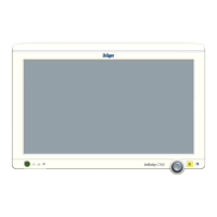
Figure 161. Installing the Flow Sensors1. Insert the flow sensors (1 in Figure 161) into the
two port connections on the breathing system,
with the electric connection on each sensor
facing down in the slot.
2. Orient the inspiratory and expiratory ports
(2 in Figure 161) so that the key on each port
lines up with the slot. Install the ports and tighten
them by turning clockwise.
Note: Flow sensors must be recalibrated after
replacement by performing the power-on self
test (see chapter “Pre-use Checkout”).
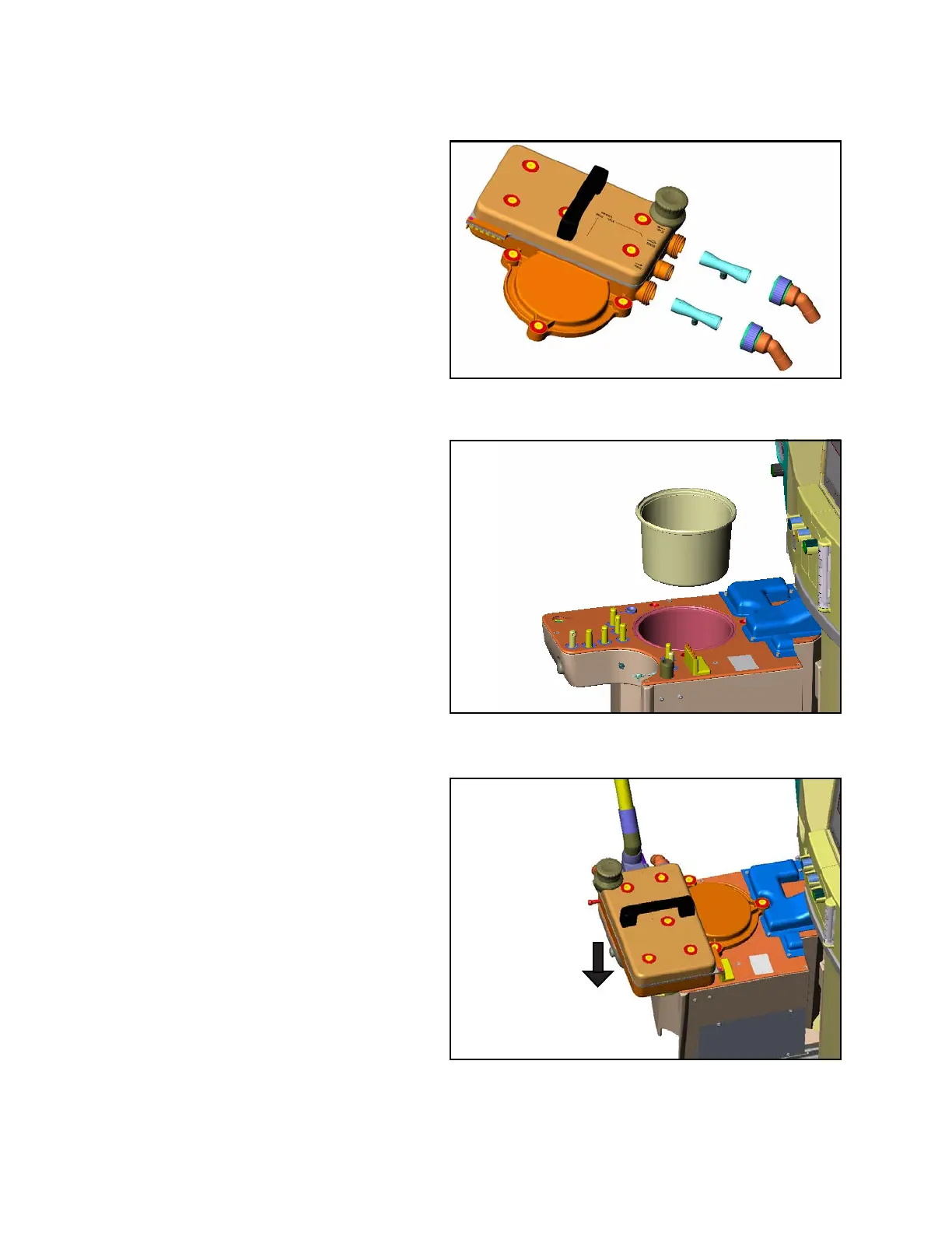
Installing the ventilator diaphragm
Figure 162. Inserting the Ventilator Diaphragm1. Insert the ventilator diaphragm so that the Dräger
legend is visible (1 in Figure 162).
Installing the breathing system
Figure 163. Installing the Breathing System1. Carefully seat the breathing system onto the
ventilator module.
2. Tighten the three sealing screws
(1 in Figure 163) on the ventilator cover.