Machine description
4812164901_A.pdf 2022-11-14
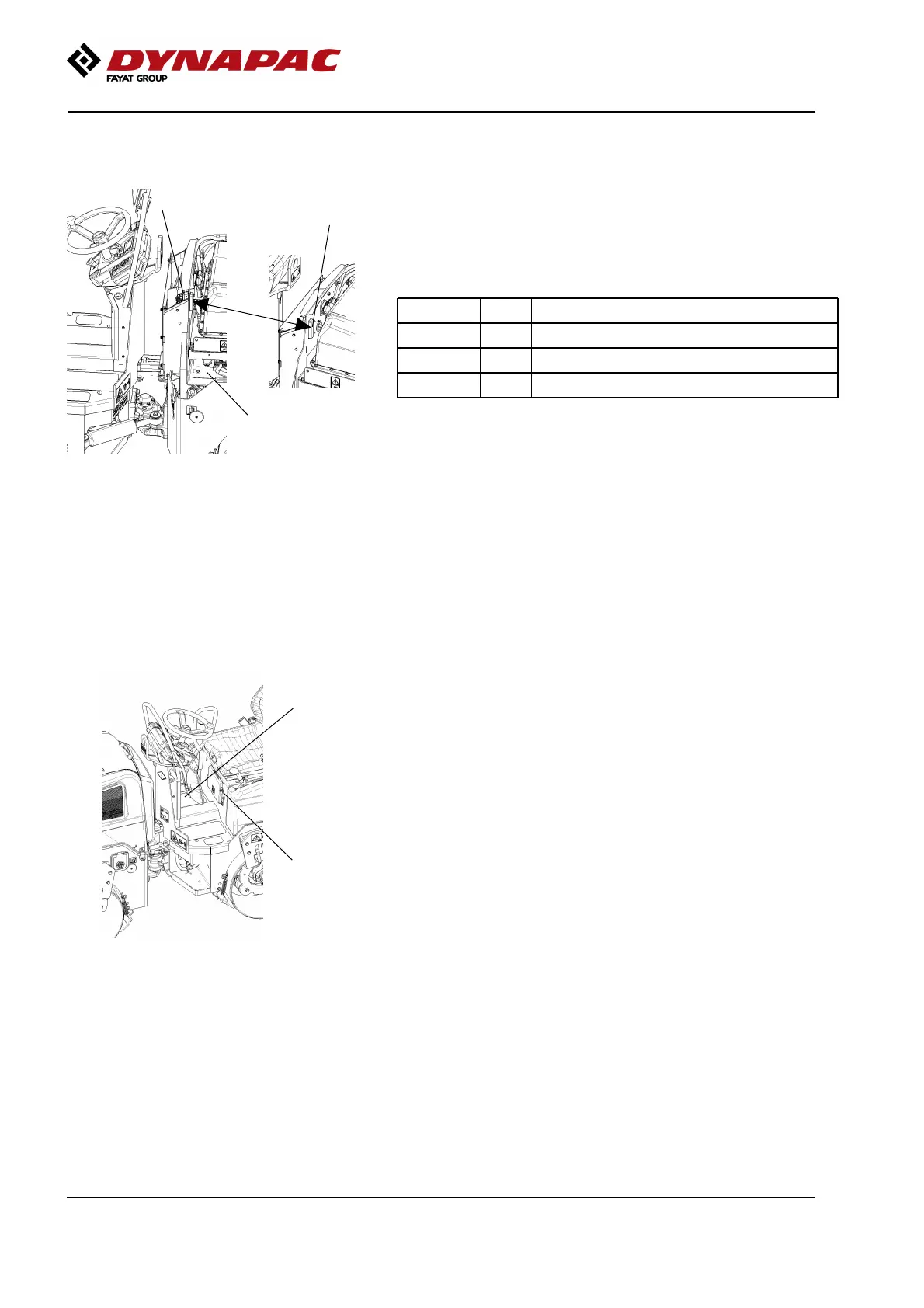
External fuses and relay
1
2
3
Fig. External fuses and relay
1. Fuse box
2. Relay (K1), forward drive/vibration
3. Relay (K3) x2, motor controls
(right/left)
The figure shows the location on the machine.
The table below gives fuse amperage and function. All
fuses are flat pin fuses.
F? 15A Main fuse convertersF? 15A Main fuse converters
F? 10A Motor controls, forward driveF? 10A Motor controls, forward drive
F? 10A Motor controls, vibrationF? 10A Motor controls, vibration
F? 40A Main fuse, circuit boardF? 40A Main fuse, circuit board
Electrical system
ECU/Circuit board
1
2
Fig. Driver’s seat
1. Control unit (ECU)
2. Circuit board
The control unit (the ECU) (1) is located behind the
document compartment on the platform.
This control unit manages, among others, automatic
vibration control, automatic watering control and
interlock.
The circuit board (2) is located behind a cover in the
steering column.
40