4.3. Mounting the Sensors
SENSORS IN USE MUST BE PROTECTED FROM MECHANICAL DAMAGE DUE TO IMPACTS OR ABRASION FOR EXAMPLE
FROM COARSE SEDIMENT LOAD OR ABRASIVE SEDIMENT MATERIAL.
Special mounting systems are available to make sensor installation easier and reduce installation time. Sensors are first
mounted to carriers that can be easily attached to any of the compatible mounting system. The signal cable is already fixed at
the sensor. The cable length has to be adapted to site conditions.
Always make sure that sensor cables connected to the transmitter are mounted firmly to the wall as tripping on the cables
can cause both serious personal injury and permanent damage to cables and connectors. Check again, that the measuring
window is not affected by the cables.
ANY ADJUSTMENTS OF CABLE LENGTHS MUST BE CARRIED OUT SOLELY BY THE MANUFACTURER. PLEASE CONTACT
OUR SERVICE TECHNICIANS.
4.3.1. Installating an Area Velocity Sensor
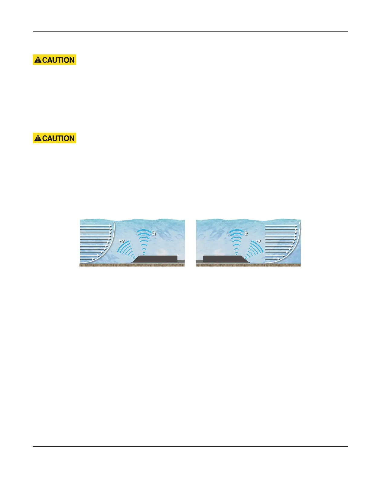
Normally, flow velocity is measured against the flow direction due to possible turbulences caused by the sensor itself and the
cable that might affect the measurement.
However, the sensor measures flow velocity regardless of the flow direction (see Figure 6). Readings measured with sensors
installed against the flow direction are registered as positive values (+v) and vice versa (-v).
Figure 6: Installation of sensors against flow direction (1) and in flow direction (2)
4.4. Calibration
For all flow velocity measuring systems for partially filled cross-sections that are installed in existing pipelines, a calibration
of the measuring site (measurement of network, tracer measurement) is recommended in order to receive an optimum
measuring accuracy. During calibration, the water level at the measuring site should be at least 4 in. (10 cm). For instructions
for calibration of measuring sites, see DIN EN ISO 748 [2].
OTE: N The calculation for calibration is performed via software in the calibration menu of user interface
( Parameter Calibration).
Installation
Page 17 March 2021 HYB-UM-03155-EN-03
 Loading...
