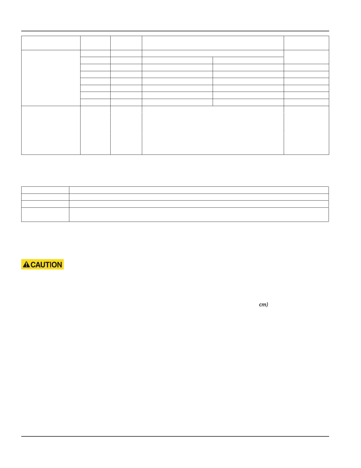
Block
No.
(row) (no.)
Name Description Cable Color
(7) AC/DC MODBUS RS-485
RS-232
4-wire 2-wire
(21) -TX -D TXD
(22) +TX +D NA
(23) -RX NA NA
(24) +RX NA RXD
(25) GND GND GND
(26) SH SH SH
(8) AC/DC
Connection area
velocity sensor
(36) T- Temperature - pink
(37) T+ Temperature + grey
(38) h- Water level - yellow
(39) h+ Water level + green
(40) v- Velocity - white
(41) v+ Velocity + brown
(42) shield
MPORTANTI
Input/output data (I/O values) are programmed in the software in the I/O main menu.
Additional elements
SIM card slot Slot for SIM card insertion / removal
LAN RJ45 socket for Ethernet connection / local LAN via RJ45 cable
LED LED control light flashes during GSM data transfer
Fuse
AC version: Fuse T2A (slow blow fuse) / 250V 5 × 20
DC version: Fuse T2A (slow blow fuse) / 250V 5 × 20
5.2. Connecting the Sensors
Sensors are connected to the connector blocks according to the specific sensor types. The voltage supply of the sensors is
provided by the transmitter.
• Before connecting or disconnecting the cable, be sure the power is switched off.
• Sensor connection must be carried out in accordance to wiring diagram, for instance the cable colors must match with
pin assignment.
• For connecting the cable sheath should only be removed for a maximum length of 1.6 in. (4 cm) .
• The stripped length of the cable has to be shorter than 0.3 in. (7 mm).
• Stranded ends should be either provided with ferrules or tinned.
• Avoid too tight clamping when attaching the cable to the transmitter. Compression of the converter cable might lead
to short-circuit between the signal and the shielding and might damage the transmitter.
• After connecting the cable, the cable bushing underneath the enclosure should be tightened.
• All cables must be installed in order to protect cables from mechanical destruction. Mount the cables firmly to the wall,
without any loops and crossovers and in sufficient distance to moving parts to avoid accidents caused by stumbling.
Electrical Connection
Page 22 March 2021HYB-UM-03155-EN-03
 Loading...
