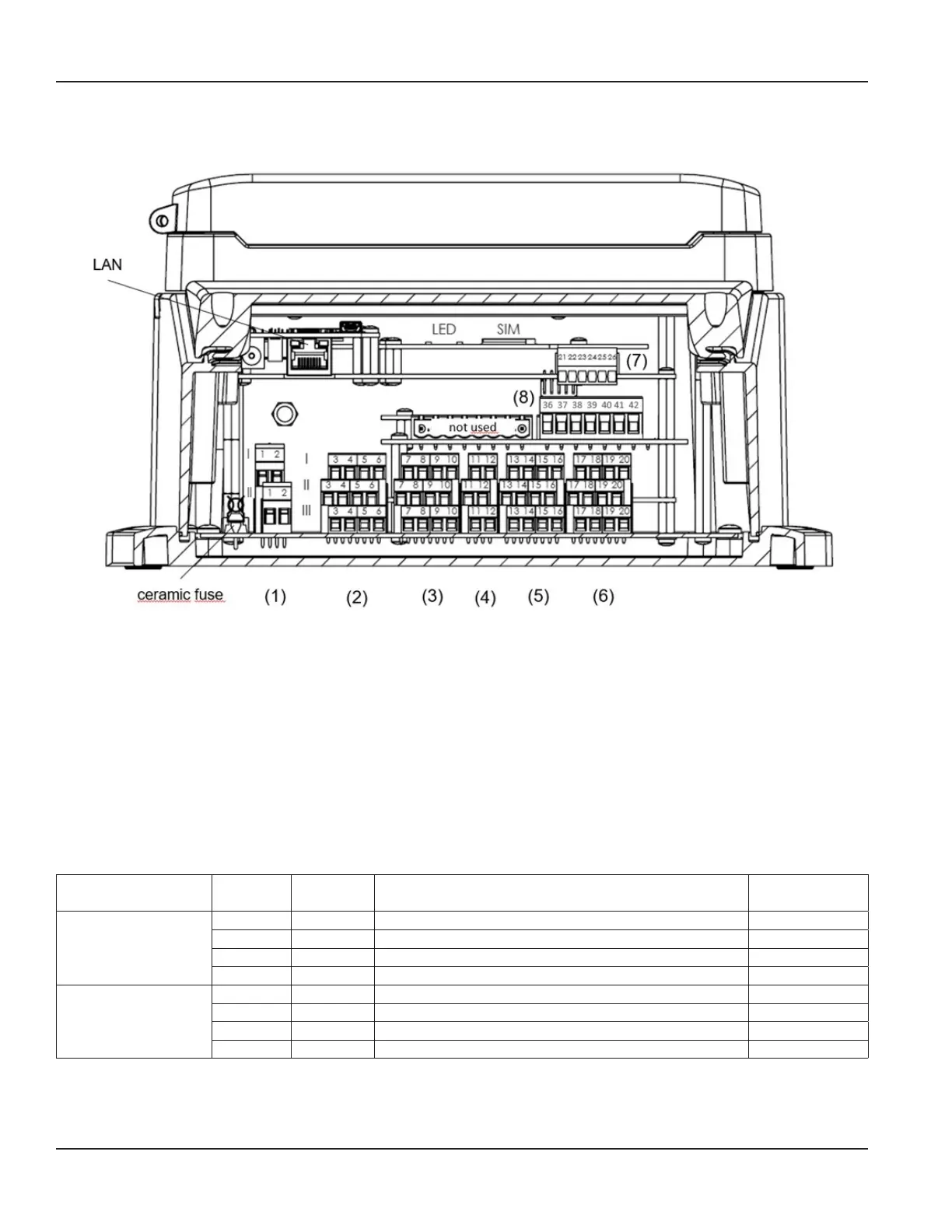
5.1.1. Pin Assignments
(1) Pins # 1-2 Power supply (AC / DC)
(2) Pins # 3-6 Relays outputs
(3) Pins # 7-10 Digital inputs /outputs
(4) Pins # 11-12 Service interface (RS-485)
(5) Pins # 13-16 Analog outputs
(6) Pins # 17-20 Analog inputs (e.g. for connection of level sensor)
(7) Pins # 21-26 MODBUS (RS-485, RS-232)
(8) Pins # 36-42 Connector block area velocity sensor
OTE: N Upon delivery, the enclosure cover is grounded with a green-yellow grounding cable.
Figure 8: Overview pin assignment
Block
No.
(row) (no.)
Name Description Cable Color
(1) AC Power Supply
(100…240V AC)
(I) (1) L Phase* Power supply Brown or Black
(II) (1) PE Protective earth; grounding terminal Green/Yellow
(I) (2) N Neutral* Power supply Blue
(II) (2) PE Protective earth; grounding terminal Green/Yellow
(1) DC Power Supply
(9…36V DC)
(I) (1) + DC In Power supply Red
(II) (1) PE Protective earth; grounding terminal Green/Yellow
(I) (2) - DC In Power supply Black
(II) (2) PE Protective earth; grounding terminal Green/Yellow
* L = external conductor, N = neutral conductor
Electrical Connection
Page 20 March 2021HYB-UM-03155-EN-03
 Loading...
