Measurement Range / Discharge calculation
Setting Description
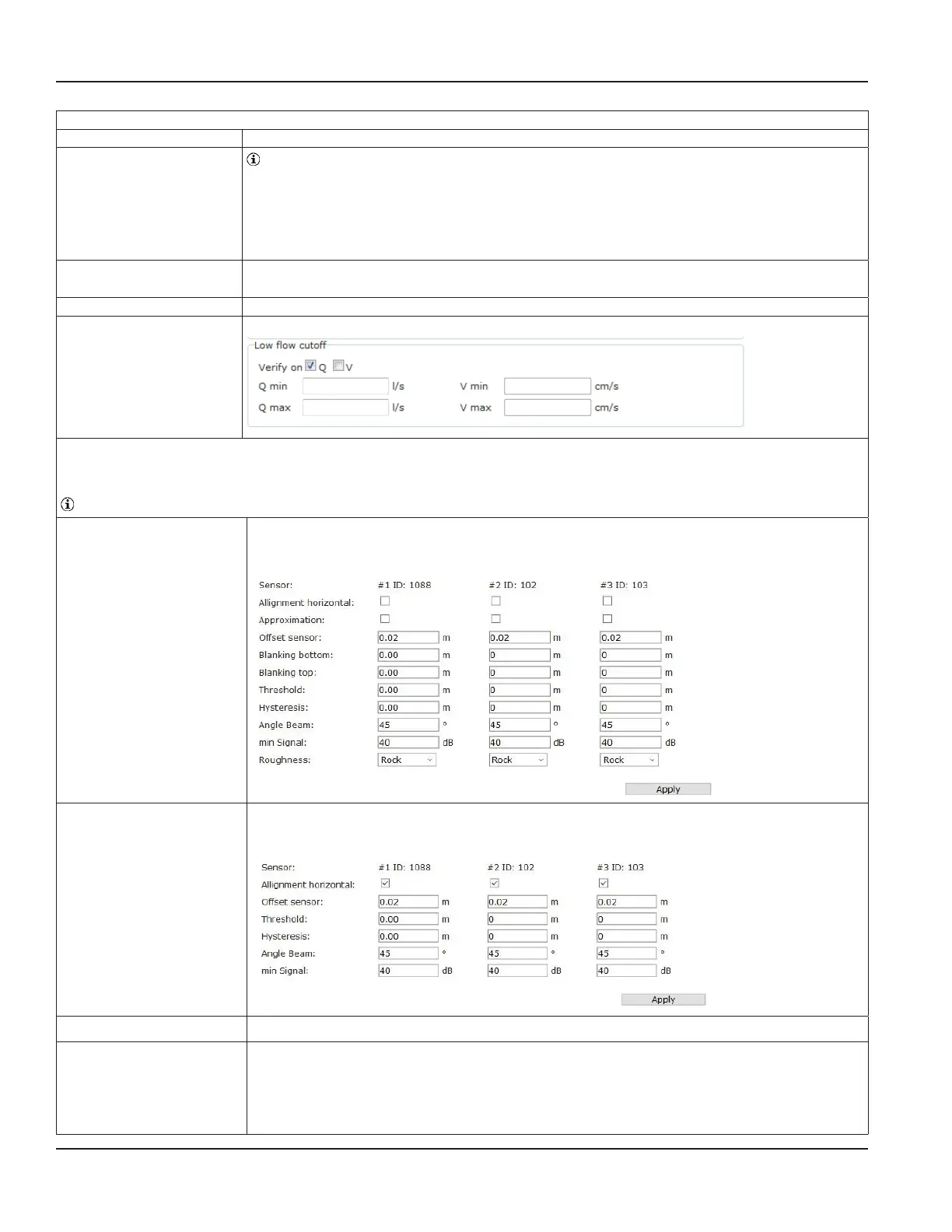
Low flow cut off
Values defined in the range of the low flow cut off are set to 0.
> Enter range of very low and therefore often unsteady discharge (Q) or velocity (v) values.
Measurement values below or within the adjustable range will be set to zero and will also be
displayed as zero on the transmitter display.
Verify on
Q / V
> Tick checkbox to choose option for Q- or V- values
Q min / Q max > Enter minimum and / or maximum for discharge value.
V min / V max > Enter minimum and / or maximum for velocity value.
Sensor parametrization
(option for connection of up to 3 area velocity sensors)
Note that sensor names (IDs #1, #2, #3) are preset by manufacturer.
Alignment horizontal
> Checkbox not activated.
Choose this option if measurement direction of area velocity sensor is vertical
(default setting).
Alignment horizontal
> Tick checkbox, if measurement direction of area velocity sensor is not vertically.
For accurate water level measurement an external water level sensor is required (see 7.7.2).
Approximation
> Tick checkbox for approximation of velocity curve.
Offset Sensor If the area velocity sensor must be installed laterally on the pipe or channel wall due to sediment
layers on the bottom the measured water level has to be adjusted (see Figure below).
> Enter difference of water level value measured by area velocity sensor and reference water
level. This value will be added to the measurement value.
Programming
Page 52 March 2021HYB-UM-03155-EN-03
 Loading...
